


Quick Research
Generate reliable direction feasibility study reports for your R&D in just a few steps.

Technical Q&A
Discover and master advanced knowledge NOW. Basics, ideas, possibilities, all at once.

Find Solutions
As an expert in R&D theories, this can generate solutions to your technical problems instantly.

Evaluate Feasibility
Analyze your overall solution with one click, know your potential R&D risks in advance.

Monitor Landscape
Get weekly tech updates, stay abreast of the latest tech innovations and key insights.
Automatic core removing device for cabbages
An automatic, cabbage technology, applied in applications, food processing, food science, etc., can solve problems such as manual movement of cabbage
- Summary
- Abstract
- Description
- Claims
- Application Information
AI Technical Summary
Problems solved by technology
Method used
Image

Examples
Embodiment 1
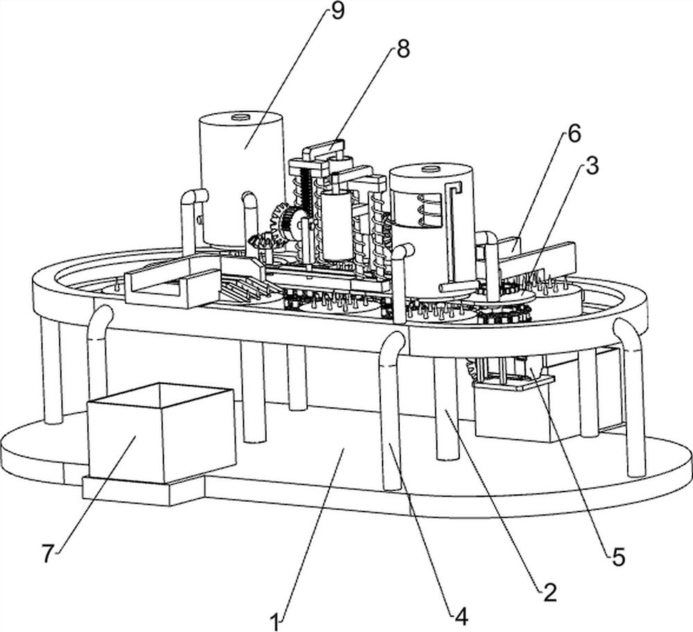
[0070] A device for automatic core removal of cabbage, such as figure 1 As shown, it includes a base plate 1, a rotating column 2, a cover plate 3, a transmission mechanism 4, a servo motor 5, a take-out path 6, a collection basket 7 and a lifting mechanism 8, and the left and right sides of the top of the base plate 1 are provided with rotating columns 2. A cover plate 3 is connected between the upper side and the top of the column 2, the transmission mechanism 4 is connected to the top of the bottom plate 1, the parts of the transmission mechanism 4 are connected to the cover plate 3, and the bottom right side of the lower cover plate 3 is connected to the servo motor 5 , the output shaft of the servo motor 5 is connected to the parts of the transmission mechanism 4, and both sides of the parts of the transmission mechanism 4 are provided with a take-out path 6, and the bottom plate 1 is equipped with a collection basket 7 on the left top front side and the right top rear sid...
Embodiment 2
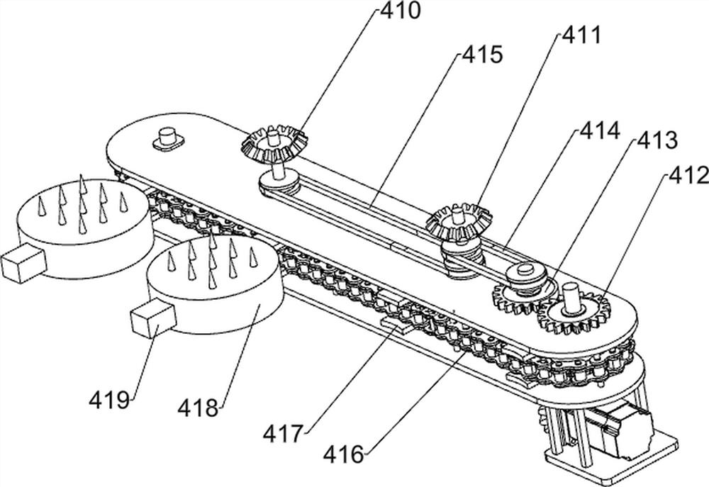
[0073] On the basis of Example 1, such as Figure 2-5 As shown, the transmission mechanism 4 includes a first supporting column 41, a slide rail 42, a first rotating shaft 43, a second rotating shaft 44, a third rotating shaft 45, a fourth rotating shaft 46, a fixed rod 47, a fifth rotating shaft 48, and a sixth rotating shaft 49. The first bevel gear set 410, the second bevel gear set 411, the full gear 412, the first missing gear 413, the first pulley combination 414, the second pulley combination 415, the sprocket combination 416, the connecting block 417, and the discharge seat 418, slider 419 and the third bevel gear set 420, the top of the base plate 1 is evenly provided with the first support column 41 in the circumferential direction, the top of the first support column 41 is connected with a slide rail 42, and the right side of the cover plate 3 is rotated. The first rotating shaft 43 is connected, the second rotating shaft 44 is rotatably connected between the left s...
Embodiment 3
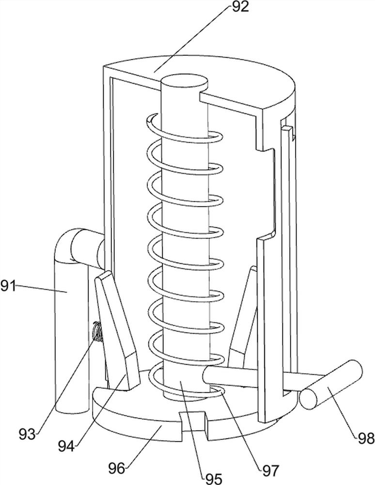
[0078] On the basis of Example 2, such as Figure 6 As shown, it also includes a pressing mechanism 9, and the pressing mechanism 9 includes a second support column 91, a pressing barrel 92, a second spring 93, a pressing block 94, a second slide bar 95, a pressing plate 96, and a third spring 97 And the handle 98, the left and right sides of the top of the upper side cover plate 3 and the left and right sides of the top of the slide rail 42 are provided with second support columns 91, the number of the second support columns 91 is 6, between the tops of the second support columns 91 on the same side Both are connected with a pressing barrel 92, the lower part of the inner wall of the pressing barrel 92 is evenly connected with a second spring 93 in the circumferential direction, the ends of the second springs 93 are connected with a pressing block 94, and the upper part of the pressing barrel 92 is slidably connected with a second slide bar 95, the bottom of the second slide ...
PUM
 Abstract
Description
Claims
Application Information
 - R&D Engineer
- R&D Manager
- IP Professional
- Industry Leading Data Capabilities
- Powerful AI technology
- Patent DNA Extraction
Browse by: Latest US Patents, China's latest patents, Technical Efficacy Thesaurus, Application Domain, Technology Topic, Popular Technical Reports.
© 2024 PatSnap. All rights reserved.Legal|Privacy policy|Modern Slavery Act Transparency Statement|Sitemap|About US| Contact US: help@patsnap.com