Low-cost high-gain broadband frequency sweep antenna

A high-gain, low-cost technology, applied in the microwave field, can solve the problems of low efficiency, narrow bandwidth, and high cost, and achieve the effects of low loss, reduced system cost, and high radiation efficiency

Pending Publication Date: 2021-10-29
珠海中科慧智科技有限公司
View PDF0 Cites 0 Cited by
  • Summary
  • Abstract
  • Description
  • Claims
  • Application Information

AI Technical Summary

Problems solved by technology

[0004] The technical problem to be solved by the present invention is: how to solve the problems of high cost, low efficiency and narrow bandwidth of existing frequency scanning antennas, and provide a low-cost high-gain broadband frequency scanning antenna

Method used


Image

  • Low-cost high-gain broadband frequency sweep antenna
  • Low-cost high-gain broadband frequency sweep antenna
  • Low-cost high-gain broadband frequency sweep antenna

Examples


Embodiment 1

[0020] This embodiment provides a technical solution: a low-cost high-gain broadband frequency-swept antenna, including a waveguide slow-wave line feed network and a column line source radiation part, the waveguide slow-wave line feed network includes a a waveguide slow wave line, and a plurality of antenna radiation units composed of collinear sources are arranged above the waveguide slow wave line.

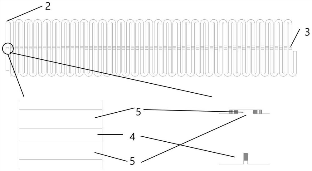
[0021] One end of the waveguide slow wave line is a signal input end, and the other end is a matching load absorption end, and the electromagnetic wave is coupled to the collinear source through the coupling structure in the slow wave line during propagation.

[0022] The coupling structure is a protruding structure periodically arranged in the waveguide, and the coupling degree is controlled by controlling the protruding height of the coupling structure and the position relative to the collinear source, thereby realizing amplitude weighting of the collinear source.

[0023] The...

Embodiment 2

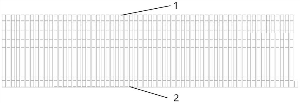
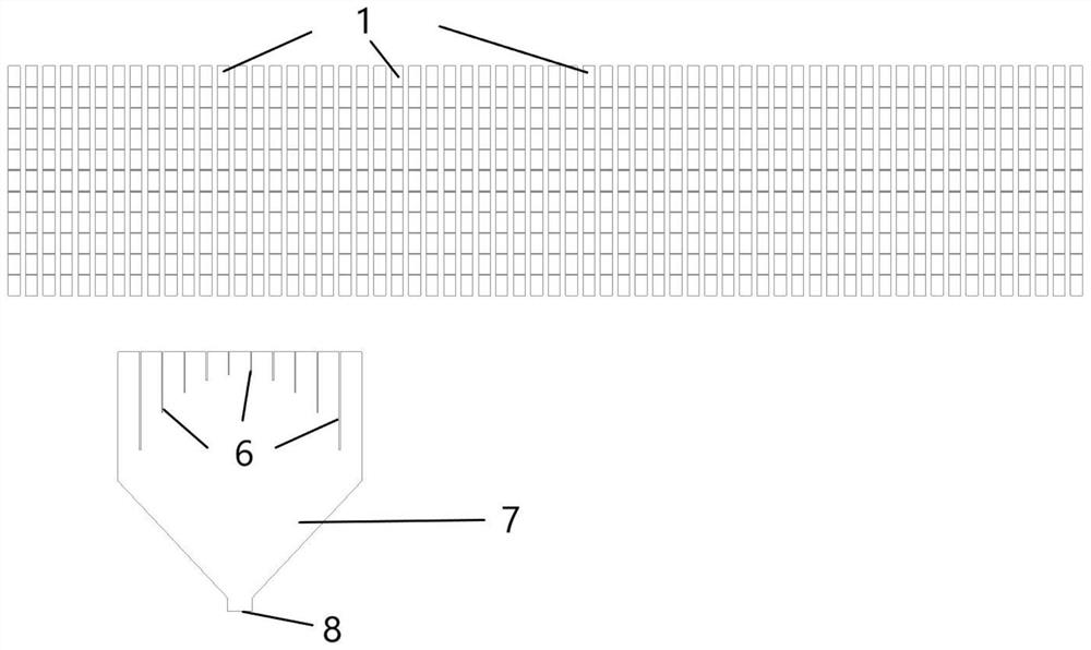
[0028] Such as figure 1 , 2 As shown, the frequency-swept array antenna of this embodiment consists of two parts, which are the column line source 1 and the waveguide slow-wave line feeding network 2 from top to bottom.

[0029] The slow wave line 2 is a waveguide structure with a coupling structure (coupling bumps and slots). The strip line is bent to form a "serpentine" line. The purpose of the "serpentine" line is to determine the distance between the column source After that, the stripline can be arranged longer in a limited space, and the scanning range of the frequency-sweeping antenna can be expanded. In a frequency-swept array antenna, the beam scanning angle and the phase difference between two adjacent column line sources in the array satisfy the following relationship:

[0030]

[0031] It can be seen that when L is constant, changing λ g , that is, the operating frequency of the radar, the phase difference between two adjacent units changes, and the beam poin...


PUM


Abstract

The invention discloses a low-cost high-gain broadband frequency sweep antenna, and belongs to the technical field of microwaves, the low-cost high-gain broadband frequency sweep antenna comprises a feed network and an antenna array plane, the feed network comprises a waveguide slow wave line and a coupling structure, and the antenna array plane comprises an opening horn antenna, a metal grid and a coupling slot. The coupling structures of the feed network are in one-to-one correspondence with the coupling gaps of the antenna array plane, and the feed network feeds the coupling gaps of the antenna array plane through the coupling structures. According to the feed network provided by the invention, the antenna array surface adopts an all-metal structure form, and the integrated compact design is realized; integrated machining is achieved, the tolerance capacity is high, and the machining cost of the whole system is greatly reduced; by adopting the design of the horn antenna and the metal grid, the high gain of the whole antenna is realized, the cost is reduced, the system performance is improved, and the antenna is worthy of popularization and application.

Description

technical field [0001] The invention relates to the field of microwave technology, in particular to a low-cost high-gain broadband frequency-scanning antenna. Background technique [0002] Due to its beam pointing and rapid beam shape change capabilities, phased array antennas are widely used in military fields such as radar, communication, and countermeasures, and civilian scenarios such as monitoring equipment. At present, there are mainly four implementation methods for phased array antennas: phase scanning, frequency scanning, delay scanning and electronic feed switch scanning. Among them, the beam steering of phased array antennas is most widely used through phase scanning and frequency scanning. Beam scanning by changing the phase of the input signal of the array element is phase scanning; by changing the frequency of the signal to change the "intra-array phase difference" between antenna elements, the scanning of the beam is frequency scanning. [0003] The existing...

Claims


Application Information

Patent Timeline
IPC IPC(8): H01Q1/36H01Q1/50H01Q13/02H01Q13/10
CPCH01Q1/36H01Q1/50H01Q13/02H01Q13/10
Inventor 唐惠琼姜胜林
Owner 珠海中科慧智科技有限公司
Why Eureka
Try Eureka