Optical fiber composite shore power cable
An optical fiber composite and cable technology, applied in the direction of power cables, power cables including optical transmission elements, and power cables including electronic control, etc. question
- Summary
- Abstract
- Description
- Claims
- Application Information
AI Technical Summary
Problems solved by technology
Method used
Image
Examples
Embodiment 1
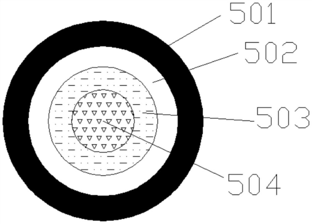
[0046]An optical fiber composite shore power cable, consisting of an outer sheath layer, a strengthening layer, 3 power line units, 1 ground line unit, 4 signal line units and 1 optical fiber unit;
[0047] Among them, the 3 power line units and 1 ground line unit adopt a short-pitch stranded structure, the stranding pitch ratio is 10, the optical fiber unit is located in the center of the power line unit and the ground line unit, and the signal line unit is located outside, the twisting is completed Finally, nylon fiber rope is used to weave to form a reinforcement layer, which is located inside the outer sheath layer, and the two together cover the power line unit, ground line unit, signal line unit, and optical fiber unit.
[0048] The outer sheath layer is composed of the following components in parts by weight:
[0049] 70 parts of fluororubber, 20 parts of carboxyl-terminated liquid fluororubber, 25 parts of chlorosulfonated polyethylene rubber, 10 parts of ethylene-viny...
Embodiment 2
[0061] Basically the same as Example 1, the difference is that the outer sheath layer is made up of the following parts by weight:
[0062] 80 parts of fluororubber, 25 parts of carboxyl-terminated liquid fluororubber, 20 parts of chlorosulfonated polyethylene rubber, 10 parts of ethylene-vinyl acetate copolymer, 10 parts of magnesium aluminum hydrotalcite, 5 parts of magnesium hydroxide, 6 parts of aluminum hydroxide, 3 parts of carbon fiber, 1 part of microcrystalline paraffin, 0.12 part of zinc stearate, 0.2 part of glycidyl methacrylate, 0.2 part of crosslinking agent DCP, 0.1 part of crosslinking agent TAIC, 0.1 part of auxiliary crosslinking agent OV-POSS.
[0063] After testing, the tensile strength is 21.1MPa, the elongation at break is 425%, the oxygen index is 31%, the water absorption rate is ≤0.1% at room temperature for 24 hours, thermal shock test (150±2°C): no cracking, low temperature impact test (-40±2 °C): no cracking.
[0064] Optical fiber paste consists o...
Embodiment 3
[0070] Basically the same as Example 1, the difference is that the outer sheath layer is made up of the following parts by weight:
[0071] 60 parts of fluororubber, 20 parts of carboxyl-terminated liquid fluororubber, 20 parts of chlorosulfonated polyethylene rubber, 10 parts of ethylene-vinyl acetate copolymer, 10 parts of magnesium aluminum hydrotalcite, 5 parts of magnesium hydroxide, 5 parts of aluminum hydroxide, 1 part of carbon fiber, 1 part of microcrystalline paraffin, 0.1 part of zinc stearate, 0.1 part of glycidyl methacrylate, 0.2 part of crosslinking agent DCP, 0.1 part of crosslinking agent TAIC, 0.1 part of auxiliary crosslinking agent OV-POSS.
[0072] After testing, the tensile strength is 21.0MPa, the elongation at break is 420%, the oxygen index is 32%, the water absorption rate is ≤0.1% at room temperature for 24 hours, the thermal shock test (150±2°C): no cracking, the low temperature impact test (-40±2 °C): no cracking.
[0073] Optical fiber paste cons...
PUM
| Property | Measurement | Unit |
|---|---|---|
| tensile strength | aaaaa | aaaaa |
| tensile strength | aaaaa | aaaaa |
| tensile strength | aaaaa | aaaaa |
Abstract
Description
Claims
Application Information
 - R&D
- Intellectual Property
- Life Sciences
- Materials
- Tech Scout
- Unparalleled Data Quality
- Higher Quality Content
- 60% Fewer Hallucinations
Browse by: Latest US Patents, China's latest patents, Technical Efficacy Thesaurus, Application Domain, Technology Topic, Popular Technical Reports.
© 2025 PatSnap. All rights reserved.Legal|Privacy policy|Modern Slavery Act Transparency Statement|Sitemap|About US| Contact US: help@patsnap.com


