Multiband space-fed radio frequency signal transmitting and receiving device and intensity calculation and measurement method

A transceiver device and radio frequency signal technology, applied in the field of radar calibration, can solve the problems of high price, large volume and weight, and difficult loading, and achieve the effect of small weight and light weight

Pending Publication Date: 2021-10-22
NANJING UNIV OF SCI & TECH
View PDF0 Cites 2 Cited by
  • Summary
  • Abstract
  • Description
  • Claims
  • Application Information

AI Technical Summary

Problems solved by technology

[0011] Whether it is a high tower, a calibration bus or a multi-rotor UAV, it is necessary to place a signal source or a signal simulator on it. These special equipment are expensive and have a certain volume and weight, especially when multi-rotor UAV calibration , due to its large size and weight, it is very difficult to carry and has a very high risk
Patent CN2017101335379 discloses a radar calibration method and system based on wireless radio frequency relay transmission technology, which discloses a wireless radio frequency relay transmission radar calibration system including radar and measured targets, and the system also includes radio frequency relay transmission Processing task load, in which the radio frequency relay transmission processing task load can be carried, so as to carry out radar calibration, but the specific structure and processing circuit of the radio frequency relay transmission processing task load are not given in the patent, let alone how to carry out Intensity and Calculation and Determination
[0012] A general principle was mentioned before, but there was no specific design and implementation of the task load device

Method used


Image

  • Multiband space-fed radio frequency signal transmitting and receiving device and intensity calculation and measurement method
  • Multiband space-fed radio frequency signal transmitting and receiving device and intensity calculation and measurement method
  • Multiband space-fed radio frequency signal transmitting and receiving device and intensity calculation and measurement method

Examples


Embodiment Construction

[0065] The present invention will be described in further detail below in conjunction with the accompanying drawings.

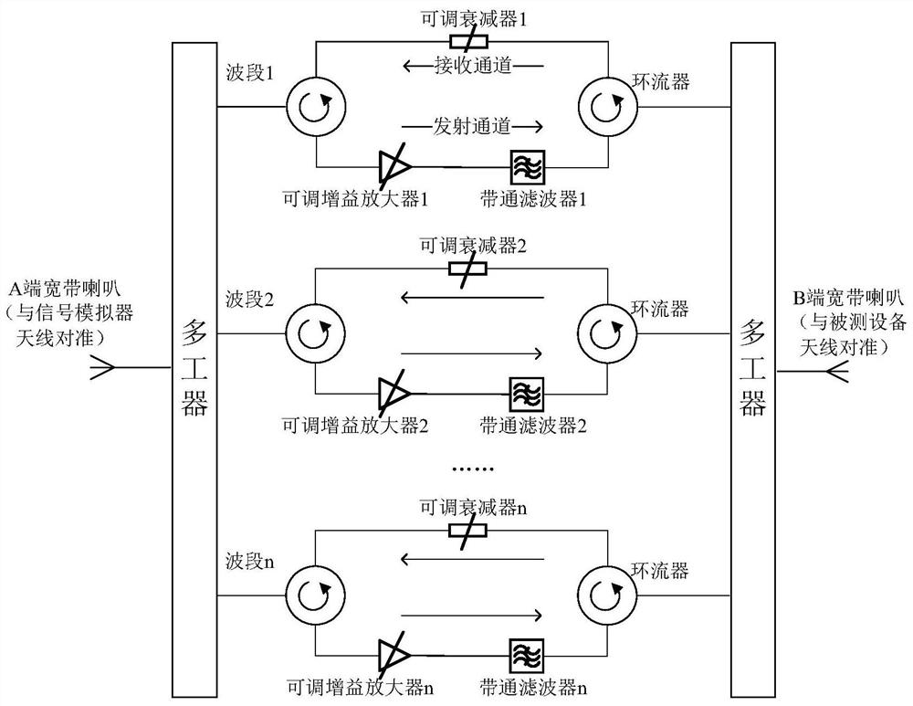
[0066] 1. Multi-band air-feed RF signal transceiver device

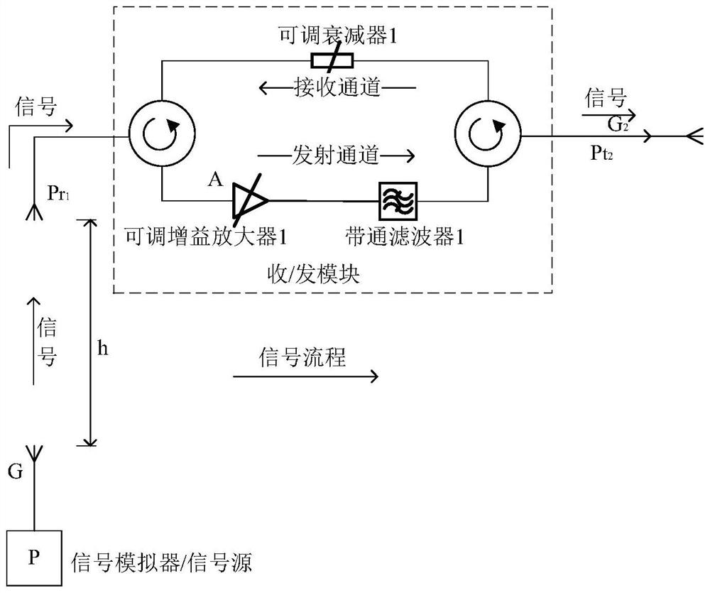
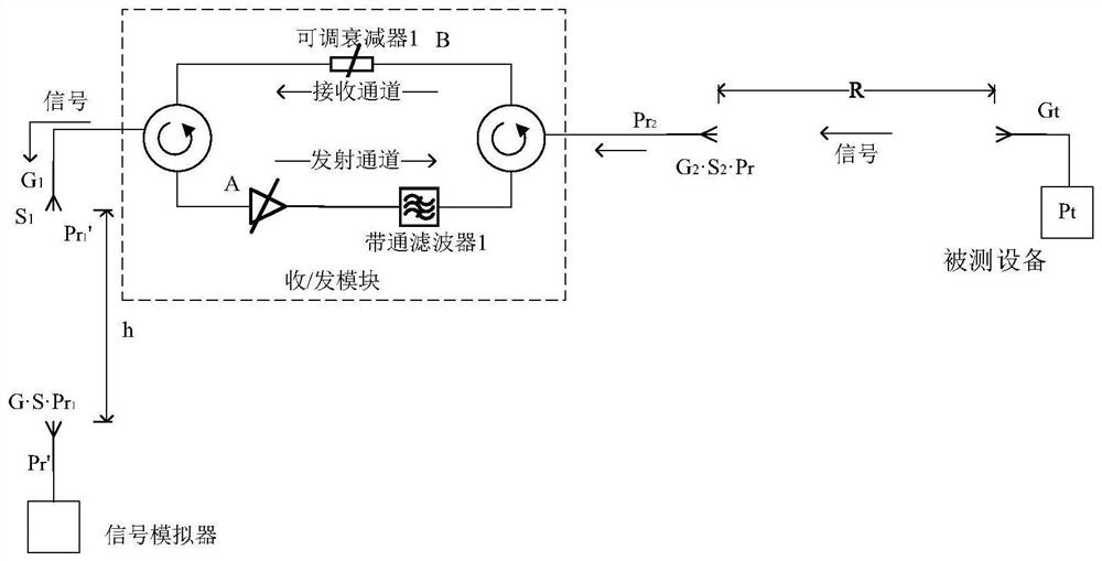
[0067] The multi-band air-feed radio frequency signal transceiver device is composed of an antenna combination and a transceiver component circuit. Wherein, the antenna combination includes two horn antennas, antenna A and B, and antenna A and B adopt broadband standard gain horn antennas.

[0068] The transceiver component circuit realizes the signal receiving and forwarding functions, and the module is composed of receiving channel, transmitting channel, circulator module, bandpass filter, adjustable attenuator, adjustable gain amplifier and so on. When receiving, the signal is filtered by the receiving channel, controlled by the gain of the adjustable attenuator, and then sent to the receiving end of the A antenna through the circulator. When transmitting, the forwarded signal is filtered and a...


PUM


Abstract

The invention belongs to the field of radar calibration, and particularly relates to a multiband space-fed radio frequency signal transmitting and receiving device and an intensity calculation and measurement method. The method comprises an antenna combination and a transceiving assembly circuit. The antenna combination comprises two broadband standard gain horn antennas, namely an antenna A and an antenna B; the transceiving component circuit integrates a radio frequency signal transceiving function of a plurality of wavebands, each waveband is provided with two signal ports, each port is connected with a circulator, and each circulator has an input / output function; and the transceiving assembly circuit is provided with two signal channels which respectively realize receiving and transmitting functions. The invention provides a gain intensity calculation method of a bidirectional propagation link and a circuit gain accurate test method of the device. The device can be installed on a lifting platform such as an airplane and a high tower, forms a link closed loop with a signal simulator and a signal source in a wireless transmission mode, completes static calibration and dynamic calibration of the radar, and has the advantages of being free of radio frequency cable linkage, small in weight, light in weight, simple, economical and the like.

Description

technical field [0001] The invention belongs to the field of radar calibration, and in particular relates to a multi-band space-feed radio frequency signal transceiver device and a strength calculation and measurement method. Background technique [0002] Radar calibration is an important means and method to verify its normal operation in the development and daily maintenance of radar. [0003] The measurement accuracy of the radar to the target determines its combat effectiveness, so it is necessary to calibrate the radar regularly and irregularly to eliminate the measurement error. The measurement error of radar includes systematic error and random error. The random error is mainly related to the signal-to-noise ratio and cannot be eliminated. The systematic error is related to the installation error, platform deformation, electromechanical axis error and navigation error. It can be obtained by comparing with the true value and be eliminated. Radar calibration is the pro...

Claims


Application Information

Patent Timeline
Patent Type & Authority Applications(China)
IPC IPC(8): G01S7/40
CPCG01S7/40
Inventor 郭剑辉邱雨珉李伦波濮存来
Owner NANJING UNIV OF SCI & TECH
Why Eureka
Try Eureka