Ultra-low NOx emission submerged combustion type gasification system capable of deeply utilizing waste heat

A technology of submerged combustion and gasification system, applied in general control systems, burners, combustion methods, etc., can solve problems such as polluting the environment and a large amount of nitrogen oxides

Pending Publication Date: 2021-10-22
JIANGSU SUNPOWER TECH
View PDF6 Cites 0 Cited by
  • Summary
  • Abstract
  • Description
  • Claims
  • Application Information

AI Technical Summary

Problems solved by technology

[0005] The purpose of the present invention is to design an ultra-low NOx emission submerged combustion gasification system with deep utilization of waste heat, aiming at the problem that a large amount of nitrogen oxides will be produced in the current liquefied natural gas gasification process and pollute the environment. By setting a flue gas denitrification device and The waste heat recovery device not only solves the problem of denitrification of flue gas, but also deeply utilizes the waste heat of flue gas after denitrification, achieving the purpose of energy saving and environmental protection

Method used


Image

  • Ultra-low NOx emission submerged combustion type gasification system capable of deeply utilizing waste heat
  • Ultra-low NOx emission submerged combustion type gasification system capable of deeply utilizing waste heat

Examples


Embodiment 1

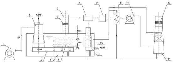
[0024] Such as figure 1 shown.

[0025] 9. An ultra-low NOx emission submerged combustion gasification system for deep utilization of waste heat. It is characterized in that it includes main fan 1, main burner 2, flue gas distributor 3, water tank 4, gasification tube bundle 5, 1# demister 6, chimney 7, auxiliary burner 8, gas mixer 9, denitrification reaction Device 10, heat exchanger 11, induced draft fan 12, scrubber 13, 2# demister 14. The gasification tube bundle 5 can use threaded tubes, internal wave and external threaded tubes, and the material is stainless steel or titanium alloy steel, etc.; the heat exchanger 11 can use special-type tube bundles such as finned tubes. The main fan 1 is connected with the main burner 2 and the auxiliary burner 8, the auxiliary burner 8 is installed in the water tank 4, the main burner 2 is connected with the flue gas distributor 3; the main burner 2, the gasification tube bundle 5, the auxiliary burner 8 is placed in the water tank...

Embodiment 2

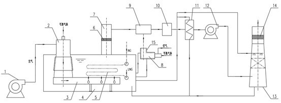
[0031] Such as figure 2 shown.

[0032] The difference between this embodiment and Embodiment 1 is that the auxiliary burner 8 is installed outside the water tank 4. At this time, a water jacket 15 should be provided outside the auxiliary burner 8, and the water from the water tank 4 is circulated in the water jacket 15. , to keep the auxiliary burner 8 cool, so as to avoid setting the refractory material inside the burner 8 . The rest are all the same as in Example 1.


PUM


Abstract

The invention relates to an ultra-low NOx emission submerged combustion type gasification system capable of deeply utilizing waste heat. The ultra-low NOx emission submerged combustion type gasification system capable of deeply utilizing the waste heat is characterized by comprising a main fan, a main combustor, a flue gas distributor, a water tank, a gasification tube bundle and the like, wherein the main fan (1) is connected with the main combustor (2) and an auxiliary combustor (8); the main combustor (2) is connected with the flue gas distributor (3); the main combustor (2), the gasification tube bundle (5) and the auxiliary combustor (8) are arranged in the water tank (4); the flue gas distributor (3) is arranged at the bottom of the water tank (4); a chimney (7) is connected with the top of the water tank (4); outlets of the chimney (7) and the auxiliary combustor (8) are connected with a gas mixer (9); the gas mixer (9), a denitration reactor (10), a heat exchanger (11), an induced draft fan (12) and a scrubber tower (13) are sequentially connected; and a reducing agent system is arranged in front of the gas mixer (9) or the denitration reactor (10). The ultra-low NOx emission submerged combustion type gasification system capable of deeply utilizing the waste heat provided by the invention is low in nitrogen oxide emission, energy-saving and environment-friendly.

Description

technical field [0001] The invention relates to a liquefied natural gas gasification technology, in particular to a gasifier technology, in particular to an ultra-low NOx emission submerged combustion gasification system for deep utilization of waste heat. Background technique [0002] In recent years, as the demand for natural gas energy has increased, the demand for liquefied natural gas (LNG) gasification has also increased. The submerged combustion gasifier is an important form of liquefied natural gas gasifier. It uses high-temperature flue gas generated by gas combustion to heat water, and then uses hot water to gasify LNG in the gasification tube bundle into natural gas (NG). The natural gas is then exported from the gasifier. [0003] Nitrogen oxides (NOx) are one of the main pollutants in the atmosphere, causing serious harm to human health, environmental ecology, and social production activities. The flue gas produced by industrial activities needs to be purified ...

Claims


Application Information

Patent Timeline
IPC IPC(8): F23D14/66B01D47/02B01D53/26B01D53/56F17C7/04F23J15/06F28D21/00G05B13/04
CPCF23D14/66F17C7/04F23J15/06G05B13/048F28D21/001B01D53/56B01D47/02B01D53/26Y02P70/10Y02E20/30Y02E20/34F17C9/02F17C13/02F23J15/04F23J15/003F17C2221/033F17C2265/05
Inventor 郭宏新刘丰张贤福刘世平何松田朝阳董海涛
Owner JIANGSU SUNPOWER TECH
Why Eureka
Try Eureka