
Fuel cell system

A fuel cell system and fuel cell stack technology, applied in fuel cells, fuel cell additives, circuits, etc., can solve problems such as the reduction of the power generation performance of the fuel cell stack, and achieve the purpose of suppressing the generation of dew condensation water and the reduction of power generation performance. Effect

Pending Publication Date: 2021-10-12
TOYOTA JIDOSHA KK
View PDF2 Cites 0 Cited by
  • Summary
  • Abstract
  • Description
  • Claims
  • Application Information

AI Technical Summary

Problems solved by technology

Moreover, if low-temperature fuel gas is supplied to the injector, and the fuel gas merges with the circulating gas containing moisture from the circulation flow path in the injector, there may be a possibility that the injector and the injector may Condensation occurs at the outlet, etc.
Moreover, if the dew condensation water enters the fuel cell stack, the power generation performance of the fuel cell stack may decrease.

Method used


Image

  • Fuel cell system
  • Fuel cell system

Examples


Embodiment Construction

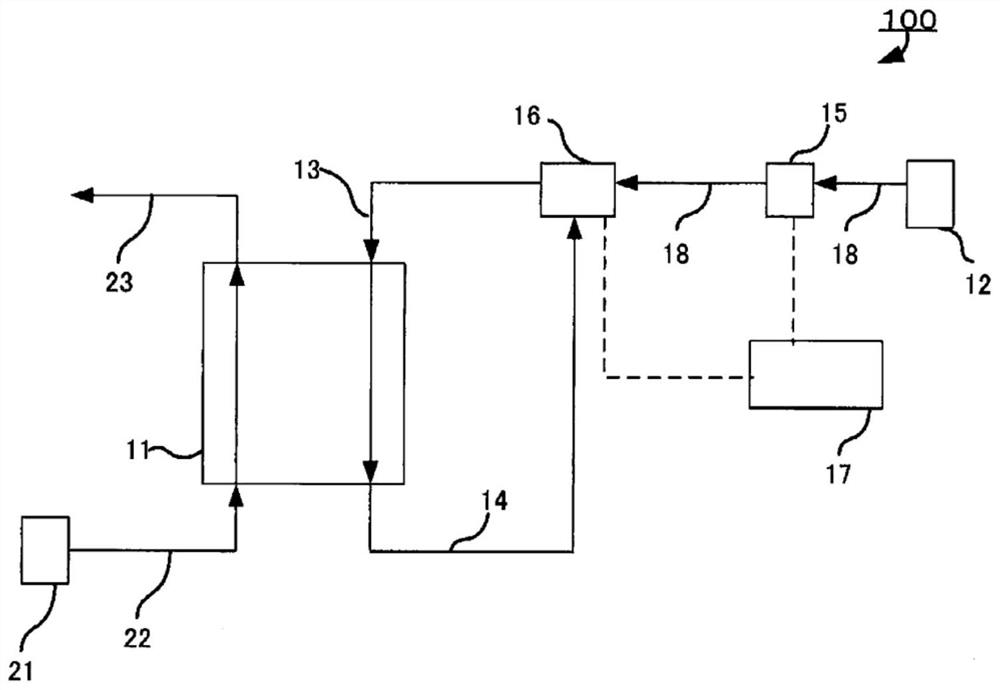
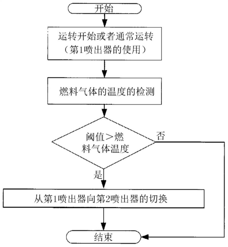
[0026] In the present disclosure, there is provided a fuel cell system characterized in that the fuel cell system includes: a fuel cell stack; an injector assembly; a fuel gas supply section for supplying fuel gas to the injector assembly; A channel for recovering the fuel off-gas discharged from the fuel cell stack, and returning it to the above-mentioned ejector collection part as circulating gas; a mixed gas supply flow path for connecting the above-mentioned ejector collection part to the above-mentioned fuel cell stack, so that A mixed gas including the fuel gas and the circulating gas is supplied from the injector assembly to each fuel electrode of the fuel cell stack; a temperature detection unit detects the temperature of the fuel gas; and a control unit, the injector The collection part has at least two injectors in parallel, wherein the first injector supplies the first mixed gas to each fuel electrode of the fuel cell stack, and the second injector supplies the circu...


PUM


Abstract

To suppress the generation of condensed water and suppress the flow of the condensed water into a fuel cell stack. A fuel cell system comprises: a fuel cell stack, an elector set, a fuel gas supplier which supplies fuel gas to the ejector set, a circulation flow path, a mixed gas supply flow path, a temperature detector which detects a temperature of the fuel gas, and a controller, wherein the ejector set includes at least two ejectors in parallel, which are a first ejector that supplies first mixed gas to the fuel electrodes of the fuel cell stack, and a second ejector that supplies second mixed gas, in which a content ratio of the circulation gas is smaller than the first mixed gas, to the fuel electrodes of the fuel cell stack.

Description

technical field [0001] The present disclosure relates to fuel cell systems. Background technique [0002] Fuel cells use hydrogen (H 2 ) and oxygen (O 2 ) electrochemical reaction, and a power generation device that extracts electric energy from a fuel cell stack (hereinafter, sometimes referred to as a battery stack) in which a plurality of single cells are stacked. In addition, in the following, fuel gas and oxidant gas may be simply referred to as "reaction gas" and "gas" without particularly distinguishing them. [0003] A unit cell of the fuel cell is generally composed of a membrane electrode assembly (MEA: Membrane Electrode Assembly) and, if necessary, two separators sandwiching both sides of the membrane electrode assembly. [0004] The membrane electrode assembly has the following configuration, that is, with protons (H + ) A conductive solid polymer electrolyte membrane (hereinafter also simply referred to as "electrolyte membrane") is formed with a catalyst l...

Claims


Application Information

Patent Timeline
IPC IPC(8): H01M8/04082H01M8/04089H01M8/0432H01M8/2457
CPCH01M8/2457H01M8/04201H01M8/04089H01M8/04097H01M8/0432H01M8/04328H01M8/04335Y02E60/50H01M8/04492
Inventor 松末真明
Owner TOYOTA JIDOSHA KK
Learn More