Alternating pole permanent magnet assisted synchronous reluctance motor for wide area operation

A technology for assisting synchronous and reluctance motors, which is applied to synchronous motors, motors, and magnetic circuits with stationary armatures and rotating magnets. problem, to achieve the effects of strong short-circuit current suppression ability, weak magnetic field speed expansion ability, and low no-load back electromotive force

Active Publication Date: 2022-04-15
NANJING UNIV OF AERONAUTICS & ASTRONAUTICS
View PDF7 Cites 0 Cited by
  • Summary
  • Abstract
  • Description
  • Claims
  • Application Information

AI Technical Summary

Problems solved by technology

[0007] However, the traditional positive salient pole internal permanent magnet motor has problems of high power density, wide speed range, anti-demagnetization ability, high reliability and low cost. The specific performance is as follows:
[0008] 1), due to L q > L d (The direct-axis reluctance is greater than the quadrature-axis reluctance). When the positive salient pole built-in permanent magnet motor uses the reluctance torque in the low-speed area, it must use a negative direct-axis current (ie -i d ), the risk of irreversible demagnetization of permanent magnets increases
[0009] 2) To reduce the risk of irreversible demagnetization, the thickness of the permanent magnet must be increased, thereby increasing the cost of permanent magnet materials (Note: Rare earth permanent magnet materials are non-renewable natural resources and strategic resources)
The increased permanent magnet thickness further reduces the direct-axis inductance (note: the field-weakening capability is closely related to the direct-axis inductance), thereby reducing the field-weakening capability and limiting the speed-expanding operating range
[0011] 4) The no-load counter electromotive force of the built-in permanent magnet motor with positive salient poles is large. If a fault occurs during high-speed operation, it may not only generate a large short-circuit current (easy to damage the motor), but may also cause weak magnetic field failure and generate feedback power generation. (easy to damage power devices in the control system, etc.), reducing reliability
[0012] In addition, in applications such as aviation power supplies and ship power supplies that require constant voltage power generation within a wide speed range, traditional surface-mounted permanent magnet motors and positive salient pole internal permanent magnet motors still face the above-mentioned problems, the most prominent of which is due to the The narrow range of constant voltage power generation and the difficulty of demagnetization due to magnetic difficulties further limit their application to occasions requiring wide-area operation

Method used


Image

  • Alternating pole permanent magnet assisted synchronous reluctance motor for wide area operation
  • Alternating pole permanent magnet assisted synchronous reluctance motor for wide area operation
  • Alternating pole permanent magnet assisted synchronous reluctance motor for wide area operation

Examples


Embodiment 1

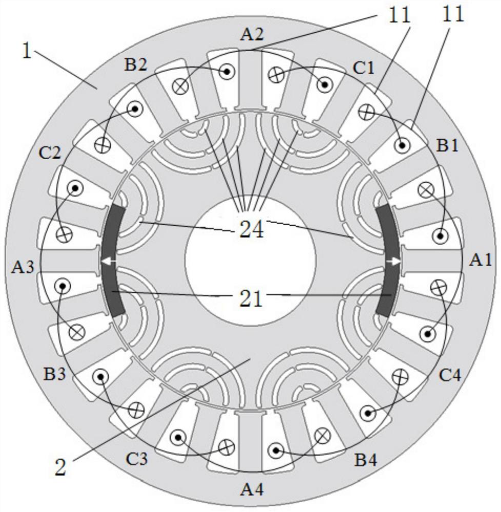
[0055] With three-phase m=3, Ns=24, p=4, p r = 3,p m =1 as an example; figure 2 shown)

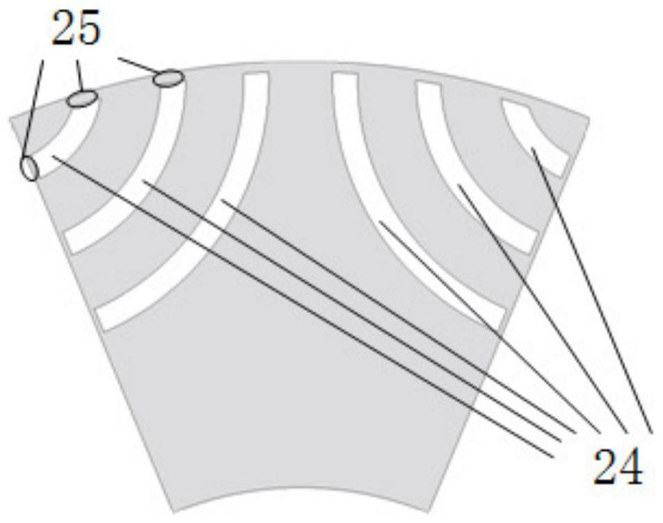
[0056] Such as figure 2 As shown, an alternating pole permanent magnet assisted synchronous reluctance motor operating in a wide area includes a stator and an alternating pole synchronous reluctance rotor arranged coaxially from the outside to the inside.

[0057] Alternatively, the alternating pole synchronous reluctance rotor can also be coaxially sleeved on the outer periphery of the stator, that is, the outer rotor.

[0058] The stator includes a stator core 1 and an armature winding 11 wound in a stator slot of the stator core.

[0059] The number of stator slots above is preferably Ns=24, and the armature winding preferably includes A, B, and C three-phase windings, wherein phase A can be formed by connecting A1, A2, A3, and A4 coils in series, or by A1-A2, A3-A4 respectively Connect in series and then in parallel; B phase and C phase and so on.

[0060] The number of pole pa...

example 2

[0072] Example 2: Permanent magnet pole offset in Example 1

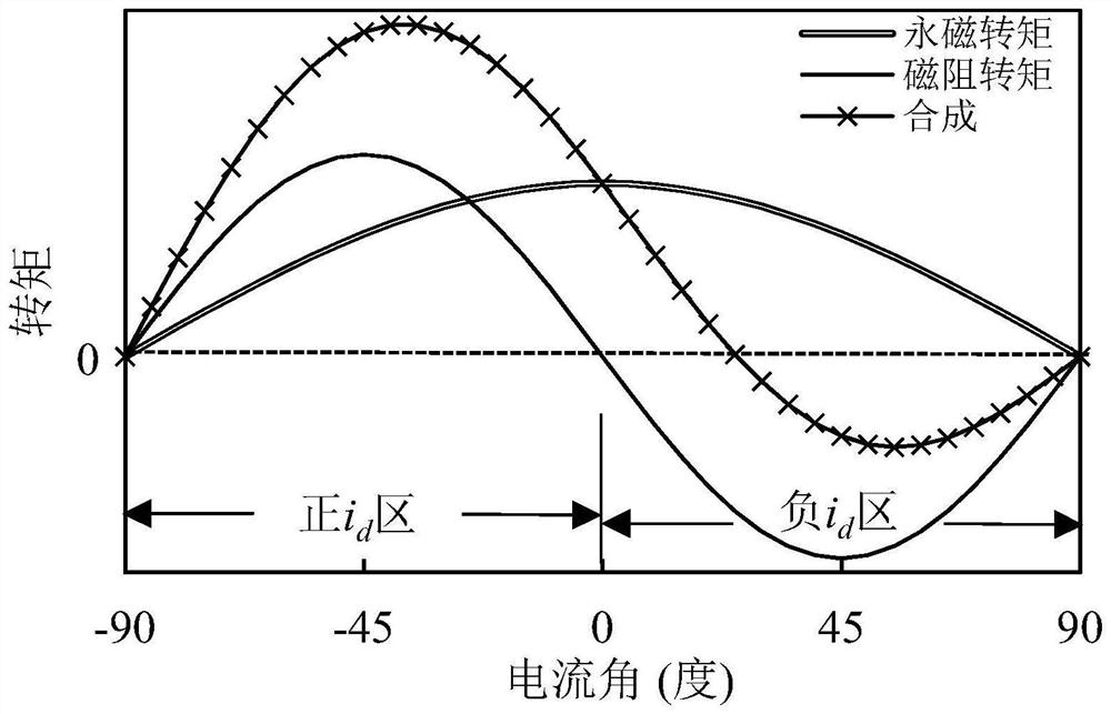
[0073] Depend on image 3 It can be seen that the permanent magnet torque reaches the maximum value when the current angle is 0 degrees, while the reluctance torque obtains the maximum value when the current angle is -45 degrees; and; low torque synthesis rate. Therefore, on the basis of Embodiment 1, this Embodiment 2 shifts the permanent magnet poles by a certain angle, specifically as Figure 4 shown.

[0074] The offset angle of the permanent magnet pole relative to the reluctance pole is preferably less than or equal to 1 / 4 pole pitch, preferably 1 / 8 of the pole pitch in this embodiment, so that the current angle at which the permanent magnet torque obtains the maximum torque approaches the reluctance rotation The torque obtains the current angle of the maximum torque (abbreviation: moment angle approximation), thereby increasing the synthesis rate of the permanent magnet torque and the reluctance torque, an...

example 3

[0076] Example 3: p=4, p r = 2, p m = 2

[0077] Such as Figure 6 As shown, there are two connected permanent magnet poles, and there are also two connected reluctance poles.


PUM


Abstract

The invention discloses an alternating pole permanent magnet assisted synchronous reluctance motor operating in a wide area, which includes a stator and an alternating pole synchronous reluctance rotor; the stator includes a stator core and an armature winding; The number of pole pairs of the pole type synchronous reluctance rotor is equal; the alternating pole type synchronous reluctance rotor includes the rotor core, and the reluctance poles and permanent magnet poles arranged on the rotor core along the circumferential direction; the number of reluctance pole pairs is greater than or equal to the permanent magnet poles. The number of pairs of magnetic poles; the direct-axis magnetic circuit of the reluctance pole is closed by the iron core, and the reluctance of the direct-axis magnetic circuit of the reluctance pole is smaller than the reluctance of the quadrature-axis magnetic circuit, so that the anti-saliency characteristic can be obtained. The present invention has anti-saliency characteristics, adopting positive i d The irreversible demagnetization of the permanent magnet can be avoided by utilizing the reluctance torque. At the same time, the direct-axis magnetic circuit of the reluctance pole is closed by the iron core, so a larger direct-axis inductance can be obtained, and the weak field speed expansion capability is stronger. In the full-speed operation range, the current angle adjustment range of the present invention is wide, so the constant power speed adjustment range can be widened.

Description

technical field [0001] The invention relates to the field of motor design and manufacture, in particular to an alternating pole permanent magnet auxiliary synchronous reluctance motor operating in a wide area. Background technique [0002] Permanent magnet motors have the advantages of high torque / power density, high efficiency and high power factor, and have been applied in many fields. According to the installation method of permanent magnets on the rotor, rotor permanent magnet motors can be divided into surface-mounted permanent magnet motors and built-in permanent magnet motors. In applications such as electric vehicles that require wide-range speed regulation (wide-area) operation, built-in permanent magnet motors are often used. [0003] The electromagnetic torque T of the permanent magnet motor e Expression, as shown in formula (1). [0004] [0005] In formula (1), p is the number of pole pairs of the motor, ψ pm is the permanent magnet flux linkage, L d and...

Claims


Application Information

Patent Timeline
Patent Type & Authority Patents(China)
IPC IPC(8): H02K1/16H02K1/24H02K1/274H02K1/276H02K21/14H02K29/00
CPCH02K1/16H02K1/246H02K1/2746H02K21/14H02K29/00H02K2213/03Y02T10/64
Inventor 李健王凯
Owner NANJING UNIV OF AERONAUTICS & ASTRONAUTICS
Why Eureka
Try Eureka