
Control device of permanent magnet synchronous motor for preventing irreversible demagnetization of permanent magnet and control system including the same

a technology of synchronous motor and control device, which is applied in the direction of electric generator control, dynamo-electric converter control, dynamo-electric gear control, etc., can solve the problems of not being able and no longer being able to generate torque from synchronous motor of permanent magnet, so as to prevent irreversible demagnetization of permanent magnet

Active Publication Date: 2015-06-09
FANUC LTD
View PDF17 Cites 2 Cited by
  • Summary
  • Abstract
  • Description
  • Claims
  • Application Information

AI Technical Summary

Benefits of technology

[0019]According to an aspect of the present invention, it is possible to prevent irreversible demagnetization of the permanent magnet of the permanent magnet synchronous motor caused by the transient current produced when the three phases of the power lines of the permanent magnet synchronous motor are short-circuited.

Problems solved by technology

When controlling a permanent magnet synchronous motor, there is a case where it is no longer possible for the permanent magnet synchronous motor to generate a torque quickly and stably due to irreversible demagnetization caused by a rise in permanent magnet temperature of a permanent magnet of the permanent magnet synchronous motor.
When the permanent magnet synchronous motor operates as a generator, there is a case where a problem, such as burn-out, occurs due to excessive voltage produced in the permanent magnet synchronous motor itself and a motor control device for controlling the permanent magnet synchronous motor.
In the conventional motor control devices described above, no measures are taken against the transient produced in the case where the three phases of the power lines of the permanent magnet synchronous motor are short-circuited, and therefore, it is not possible to prevent irreversible demagnetization of the permanent magnet of the permanent magnet synchronous motor caused by the transient current produced in the case where the three phases of the power lines of the permanent magnet synchronous motor are short-circuited.

Method used


Image

  • Control device of permanent magnet synchronous motor for preventing irreversible demagnetization of permanent magnet and control system including the same
  • Control device of permanent magnet synchronous motor for preventing irreversible demagnetization of permanent magnet and control system including the same
  • Control device of permanent magnet synchronous motor for preventing irreversible demagnetization of permanent magnet and control system including the same

Examples


Embodiment Construction

[0030]Embodiments of the motor control device according to the present invention are explained with reference to the drawings. In the drawings, the same symbols are attached to the same components.

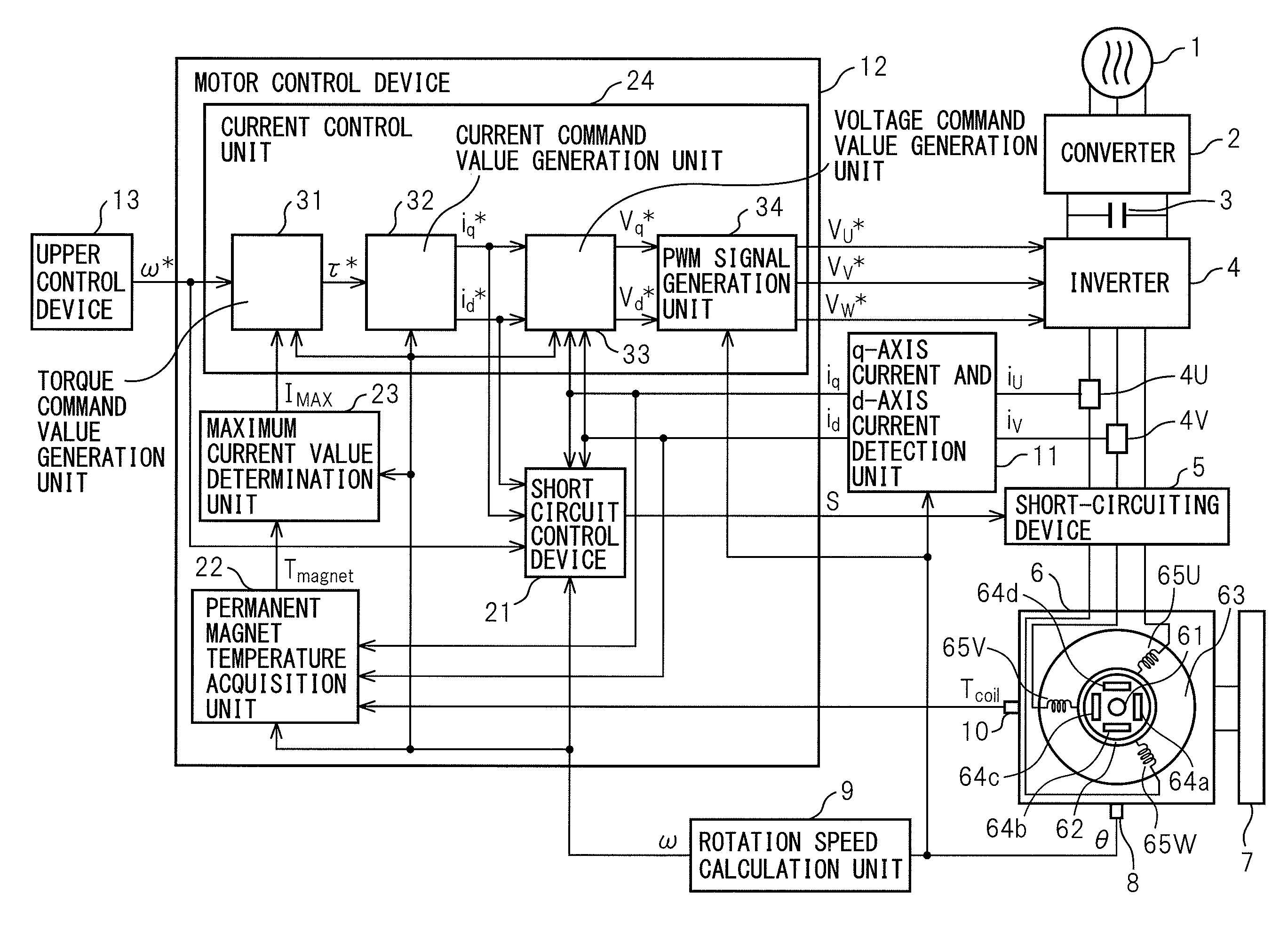
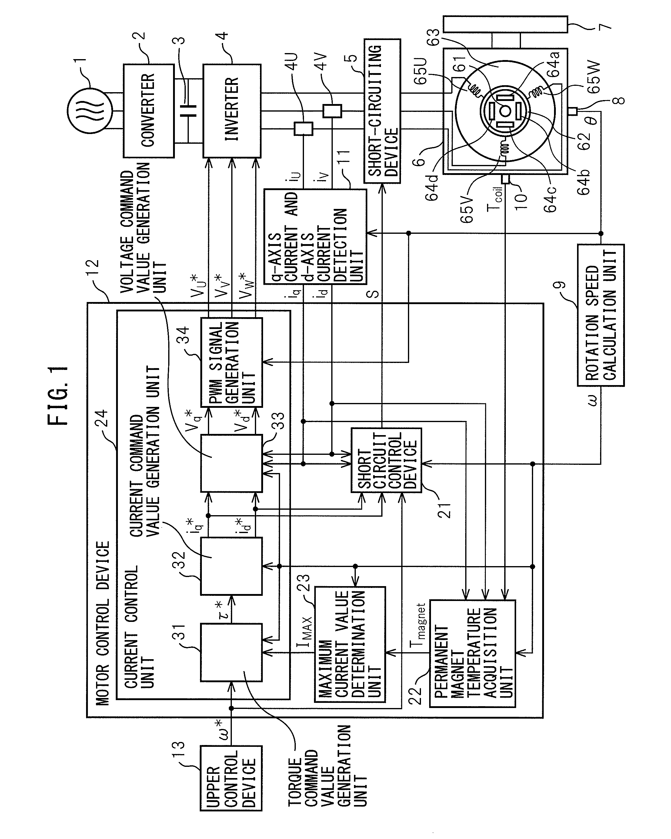
[0031]Referring to the drawings, FIG. 1 is a block diagram of a control system having a motor control device of an embodiment of the present invention. The control system illustrated in FIG. 1 has a three-phase alternating-current power source 1, a converter 2, a smoothing capacitor 3, an inverter 4, a short-circuiting device 5, a permanent magnet synchronous motor 6, a driven object 7, a rotation angle sensor 8, a rotation speed calculation unit 9, a coil temperature sensor 10, a q-axis current and d-axis current detection unit 11, a motor control device 12, and an upper control device 13.

[0032]The converter 2 consists of a plurality (six, in the case of three-phase alternating current) of rectifier diodes, for example, and converts alternating-current power supplied from the three-phase ...


PUM


Abstract

A maximum current value determination unit determines the maximum current value of a permanent magnet synchronous motor in order to prevent irreversible demagnetization of a permanent magnet of the permanent magnet synchronous motor from occurring due to transient current occurring at the time of short-circuiting of three phases, based on one of a set of irreversible demagnetization causing current value corresponding to permanent magnet temperature and the transient current occurring at the time of the short-circuiting of three phases, and a set of irreversible demagnetization causing magnetic field intensity corresponding to the permanent magnet temperature and demagnetization field intensity of the permanent magnet of the permanent magnet synchronous motor occurring at the time of the short-circuiting of three phases. A current control unit controls the current of the permanent magnet synchronous motor so that the current value of the permanent magnet synchronous motor is less than the maximum current value.

Description

RELATED APPLICATIONS[0001]The present application is based on, and claims priority from, Japanese Application Number 2012-196402, filed Sep. 5, 2012, the disclosure of which is hereby incorporated by reference herein in its entirety.BACKGROUND OF THE INVENTION[0002]1. Field of the Invention[0003]The present invention relates to a control device of a permanent magnet synchronous motor for preventing irreversible demagnetization of a permanent magnet of a permanent magnet synchronous motor, and a control system including such a control device.[0004]2. Description of Related Art[0005]When controlling a permanent magnet synchronous motor, there is a case where it is no longer possible for the permanent magnet synchronous motor to generate a torque quickly and stably due to irreversible demagnetization caused by a rise in permanent magnet temperature of a permanent magnet of the permanent magnet synchronous motor. Because of this, various kinds of motor control devices for preventing irr...

Claims


Application Information

Patent Timeline
Patent Type & Authority Patents(United States)
IPC IPC(8): H02P9/00H02P3/22H02P29/00H02P27/04H02P21/00H02P21/36
CPCH02P3/22H02P29/0066H02P29/662
Inventor KAWAI, KENJI
Owner FANUC LTD
Learn More