
Offshore thermal recovery heavy oil gathering and transportation treatment process package

A processing technology and thermal recovery technology, applied in the field of offshore thermal recovery heavy oil development engineering, can solve the problems of difficult dehydration of heavy oil, damage to equipment and sea pipes, large changes in liquid volume, etc., so as to improve the oil-water separation efficiency and shorten the residence time. , the effect of efficient processing equipment

Pending Publication Date: 2021-10-08
CHINA NAT OFFSHORE OIL CORP +1
View PDF0 Cites 2 Cited by
  • Summary
  • Abstract
  • Description
  • Claims
  • Application Information

AI Technical Summary

Problems solved by technology

After the heavy oil is recovered from the formation, there are three main problems in the process of treatment. On the one hand, due to the high viscosity of the heavy oil and the small difference in oil-water density, it is very difficult to dehydrate the heavy oil; on the other hand, the thermal recovery of heavy oil is usually divided into During a series of processes such as heat injection, well braising, and blowout, the gas-liquid volume and temperature of the produced fluids vary greatly, especially during the blowout period. Equipment and sea pipes are damaged, and due to the high viscosity of heavy oil, the direct use of cyclone desander for heavy oil is not effective in removing sand

Method used


Image

  • Offshore thermal recovery heavy oil gathering and transportation treatment process package

Examples


Embodiment Construction

[0041] The experimental methods used in the following examples are conventional methods unless otherwise specified.

[0042] The materials and reagents used in the following examples can be obtained from commercial sources unless otherwise specified.

[0043] Below, the present invention is illustrated by taking a certain heavy oil field development process package in Bohai Sea as an example. The oil treatment capacity of this process package is 1909m 3 / d, using jet pump for oil extraction.

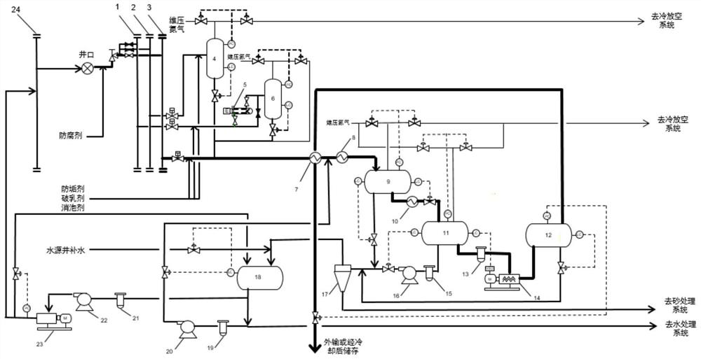
[0044] Such as figure 1 As shown, it is a schematic diagram of a heavy oil gathering and transportation treatment process package provided by the present invention, including: metering manifold 1, blowout manifold 2, production manifold 3, spray tank 4, metering heater 5, metering separation 6. Qualified crude oil / water-containing crude oil heat exchanger 7. First production heater 8. Electrostatic coalescence primary separator 9. Second production heater 10. Electrostatic coalescence ...


PUM


Abstract

The invention discloses an offshore thermal recovery heavy oil gathering and transportation treatment process package. The offshore thermal recovery heavy oil gathering and transportation treatment process package is structurally characterized in that a metering manifold, a blowout manifold and a production manifold are connected with a thermal recovery wellhead Christmas tree, and a cold flow outlet of a qualified crude oil / water-containing crude oil heat exchanger is sequentially connected with a first production heater, an electrostatic coalescence primary separator, a second production heater and an electrostatic coalescence secondary separator; an oil phase outlet of the electrostatic coalescence secondary separator is sequentially connected with an electric dehydration pump front filter and an electric dehydration booster pump, an outlet of the electric dehydration booster pump is connected with an inlet of an electric dehydrator, the oil phase outlet is connected with a heat flow inlet of the qualified crude oil / water-containing crude oil heat exchanger, and qualified crude oil produced by the heat flow outlet of the qualified crude oil / water-containing crude oil heat exchanger is transported outwards through a pump or cooled and then stored; and water phase outlets of the electrostatic coalescence primary separator, the electrostatic coalescence secondary separator and the electric dehydrator are connected with a cyclone desander and then a water treatment system. The offshore thermal recovery heavy oil gathering and transportation treatment process package can be widely applied to the technical field of offshore heavy oil thermal recovery development engineering.

Description

technical field [0001] The invention relates to a process package for gathering and transporting heavy oil from offshore thermal recovery, and belongs to the technical field of heavy oil development engineering from offshore thermal recovery. Background technique [0002] Heavy oil has high viscosity and high density. Steam huff and puff and steam flooding are often used in development, that is, high-temperature and high-pressure water vapor is injected into the formation, and the viscosity of crude oil in the formation is reduced by heating to extract the heavy oil from the formation. After the heavy oil is recovered from the formation, there are three main problems in the process of treatment. On the one hand, due to the high viscosity of the heavy oil and the small difference in oil-water density, it is very difficult to dehydrate the heavy oil; on the other hand, the thermal recovery of heavy oil is usually divided into During a series of processes such as heat injection...

Claims


Application Information

Patent Timeline
IPC IPC(8): E21B43/24E21B43/34
CPCE21B43/24E21B43/35
Inventor 张明王海燕王春升郑晓鹏尚超杨天宇杨泽军刘人玮平朝春王艳红
Owner CHINA NAT OFFSHORE OIL CORP
Learn More