
Automobile metal plate stamping die

A stamping die and sheet metal technology, applied in the field of automobile sheet metal processing, can solve the problems of sheet metal deformation, uneven force on the sheet metal, and deterioration of the quality of the sheet metal, so as to achieve uniform force and full utilization. , avoid wasteful effects

Pending Publication Date: 2021-10-08
李玉祥
View PDF1 Cites 2 Cited by
  • Summary
  • Abstract
  • Description
  • Claims
  • Application Information

AI Technical Summary

Problems solved by technology

[0005] The above-mentioned comparative patent presses the end of the L-shaped blanking top block in the L-shaped blanking chute away from the pressure mold plate, and the end of the L-shaped blanking top block away from the pressure mold plate is pressed, and the L-shaped blanking top block is located at One end of the top of the L-shaped chute is lifted, so that the sheet metal parts adhered to the pressure mold plate are pushed away, and the staff can slide the sheet metal parts from the pressure mold plate through the limit roller Take it out, but in the actual operation process, one side of the sheet metal part is jacked up, causing the sheet metal part to be stressed unevenly, resulting in deformation of the sheet metal part, which in turn leads to a decrease in the quality of the sheet metal part

Method used


Image

  • Automobile metal plate stamping die
  • Automobile metal plate stamping die
  • Automobile metal plate stamping die

Examples


Embodiment Construction

[0032] The following will clearly and completely describe the technical solutions in the embodiments of the present invention with reference to the accompanying drawings in the embodiments of the present invention. Obviously, the described embodiments are only some, not all, embodiments of the present invention. Based on the embodiments of the present invention, all other embodiments obtained by persons of ordinary skill in the art without making creative efforts belong to the protection scope of the present invention.

[0033] see Figure 1 to Figure 8 , the present invention provides a technical solution:

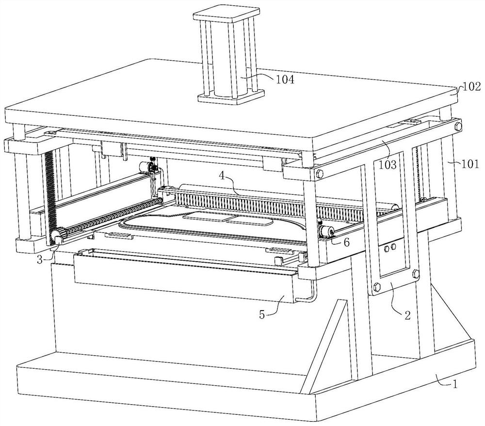
[0034] An automobile sheet metal stamping die, such as Figure 1 to Figure 4 As shown, the mold body 1 is included, and the top four corners of the mold body 1 are fixedly connected with support rods 101, and the upper ends of the four support rods 101 are jointly fixedly connected with a support plate 102, and the top center of the support plate 102 is A hydraulic cyli...


PUM


Abstract

The invention relates to the technical field of automobile metal plate part processing, in particular to an automobile metal plate stamping die. The die comprises a die body, supporting rods are fixedly connected to the four corners of the top end of the die body, a supporting plate is jointly and fixedly connected to the upper ends of the four supporting rods, and a hydraulic cylinder is fixedly installed in the center of the top end of the supporting plate; and the lower end of the hydraulic cylinder penetrates through the supporting plate, a die pressing plate is fixedly connected to the lower end of the hydraulic cylinder, the die pressing plate is slidably connected with the supporting rods, and a lifting mechanism is fixedly connected to the upper end of the die pressing plate. According to the device, in combination with the lifting mechanism, a stamping-formed metal plate part is conveniently taken down from the device, the metal plate part does not need to be manually removed from the die from the front end and the rear end, ad thus waste of manpower resources is avoided; the metal part plate is removed from the die from the four corners, stress on the metal plate part is more uniform during die removing, deformation of the metal plate part due to uneven stress during die removing is avoided, and the effect of the metal plate part can be effectively guaranteed.

Description

technical field [0001] The invention relates to the technical field of automobile sheet metal parts processing, in particular to an automobile sheet metal stamping die. Background technique [0002] Automobile sheet metal is a technical means of automobile repair. In this respect, automobile sheet metal is equal to automobile sheet metal repair. It refers to the repair of the car body after a car collision, that is, all the work except for the spraying work of anti-corrosion and decoration of the car body. . Such as the analysis of car body damage, the measurement of car body, the shaping of car body sheet metal, stretch correction, stress relief welding, and the assembly and adjustment of car body accessories. [0003] Stamping die is a special process equipment for processing materials (metal or non-metal) into parts (or semi-finished products) in cold stamping processing, called cold stamping die (commonly known as cold stamping die). Stamping is a pressure processing m...

Claims


Application Information

Patent Timeline
IPC IPC(8): B21D43/00B21D45/08B21D37/18B08B1/00B01D29/01B01D29/90B01D29/64
CPCB21D43/003B21D45/08B21D37/18B01D29/01B01D29/90B01D29/64B08B1/30B08B1/12
Inventor 李玉祥李鹏举
Owner 李玉祥
Learn More