Hydraulic oil recovery processing device
A technology for recycling and processing hydraulic oil, applied in filter circuits, liquid separation, mixers, etc., which can solve problems such as environmental pollution, poor safety and reliability, and uncontrollable water discharge speed.
- Summary
- Abstract
- Description
- Claims
- Application Information
AI Technical Summary
Problems solved by technology
Method used
Image

Examples
specific Embodiment approach 1
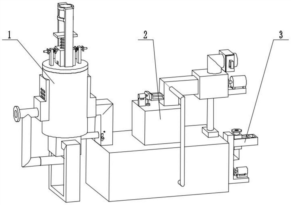
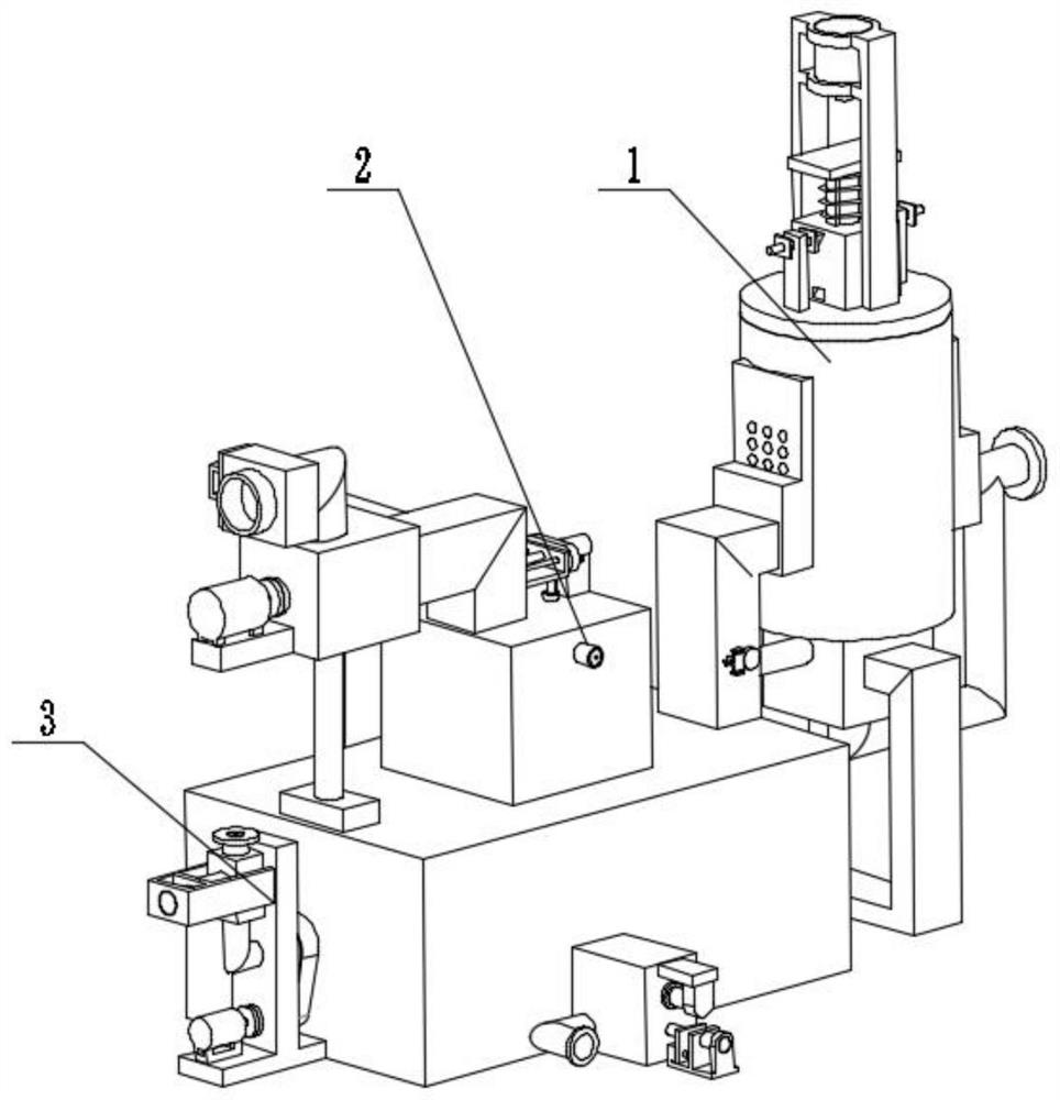
[0037] Combine below Figure 1-18 Describe this embodiment. The present invention relates to a hydraulic oil treatment device, more specifically a hydraulic oil recovery treatment device, which includes a sludge removal mechanism 1, a water and poison removal mechanism 2, and an additive addition mechanism 3. The device can treat waste The hydraulic oil is filtered safely. The device can visually observe the operation status of the filter holes. The device can preserve the hydraulic oil for a long time. The device can accelerate the separation of water and oil and help the water to be discharged quickly. The device can add additives and mix them evenly.
[0038] The sludge removal mechanism 1 is connected with the water and poison removal mechanism 2, and the water and poison removal mechanism 2 is connected with the additive adding mechanism 3;
[0039] The sludge removal mechanism 1 includes a support 1-1, a connecting pipe 1-2, a pressure relief safety pipe 1-3, a filter bo...
specific Embodiment approach 2
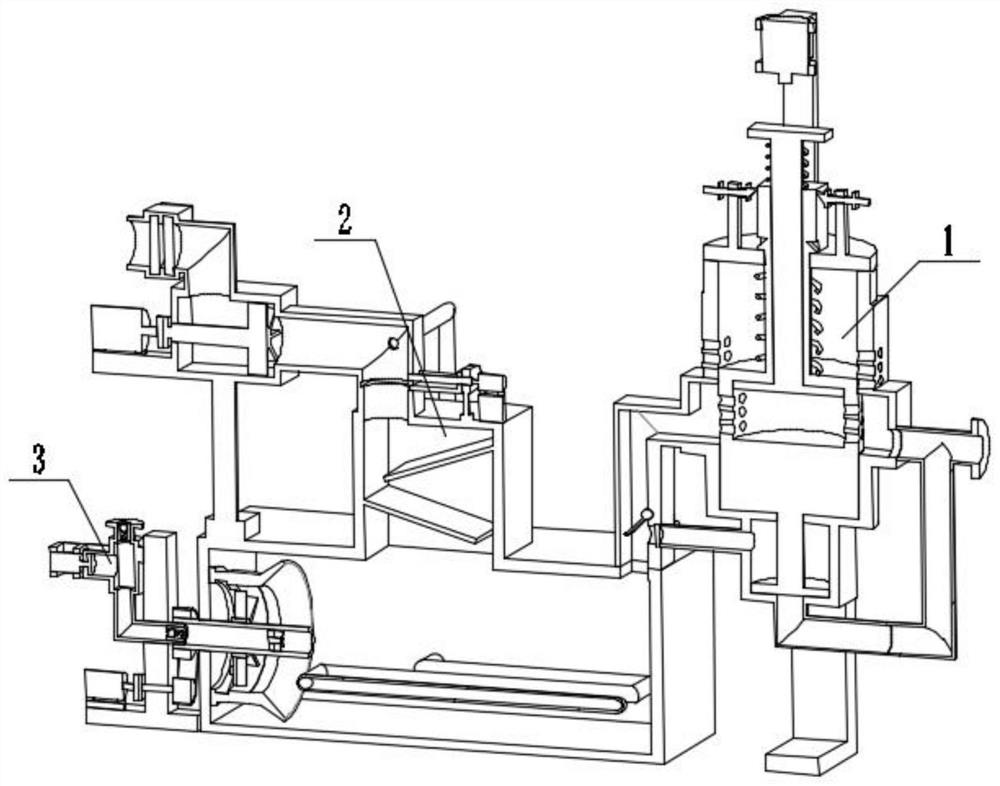
[0040] Combine below Figure 1-18Describe this embodiment, this embodiment will further explain Embodiment 1, the described water removal and detoxification mechanism 2 includes a water removal tank 2-1, a water removal tank inlet 2-2, a connecting heat exchange tube 2-3, a servo motor 2- 4. Bearing seat 2-5, movable gate 2-6, lead screw 2-7, second limit rod 2-8, connection box 2-9, air duct 2-10, multi-layer filter plate 2-11, impeller Drive motor 2-12, first coupling 2-13, pressure relief pipe 2-14, pressure relief valve 2-15, switching box 2-16, plug 2-17, second hydraulic cylinder 2-18, hydraulic Cylinder support 2-19, double-sided plug 2-20, oil output pipe 2-21, impeller with shaft 2-22, gate groove 2-23, oil baffle plate 2-24, inner plug fitting hole 2-25, Switching pipe 2-26, inner plug 2-27, second hydraulic rod 2-28, first socket 2-29, second socket 2-30, water removal tank 2-1 is provided with water removal tank inlet 2-2, The inlet 2-2 of the water removal tank ...
specific Embodiment approach 3
[0041] Combine below Figure 1-18 Describe this embodiment, this embodiment will further explain the first embodiment, the additive adding mechanism 3 includes a rotating tube 3-1, a tapered ring 3-2, a narrowing ring 3-3, a ring fixing seat 3-4, Pulley 3-5, belt 3-6, support seat 3-7, additive inlet pipe 3-8, liquid inlet check valve 3-9, cross brace 3-10, fixed elbow 3-11, second coupling 3-12, motor 3-13, belt pulley 3-14, drawer box 3-15, third hydraulic cylinder 3-16, return impeller 3-17, second piston with rod 3-18, liquid outlet one-way Valve 3-19, accelerating impeller 3-20, rotating tube 3-1 and conical ring 3-2 coaxial center, conical ring 3-2 links to each other with narrowing ring 3-3, narrowing ring 3-3 and ring Fixed seat 3-4 links to each other, rotating tube 3-1 links to each other with belt pulley 3-5, belt pulley 3-5 is frictionally connected with belt 3-6, belt 3-6 is frictionally connected with belt shaft pulley 3-14, belt shaft belt pulley 3- 14 is rota...
PUM
 Abstract
Description
Claims
Application Information
 - Generate Ideas
- Intellectual Property
- Life Sciences
- Materials
- Tech Scout
- Unparalleled Data Quality
- Higher Quality Content
- 60% Fewer Hallucinations
Browse by: Latest US Patents, China's latest patents, Technical Efficacy Thesaurus, Application Domain, Technology Topic, Popular Technical Reports.
© 2025 PatSnap. All rights reserved.Legal|Privacy policy|Modern Slavery Act Transparency Statement|Sitemap|About US| Contact US: help@patsnap.com