
Sparse array optimization method based on arrangement discrete differential evolution algorithm

A sparse array and evolutionary algorithm technology, applied in genetic rules, gene models, instruments, etc., can solve the problems of high maximum sidelobe level, reducing the sensitivity of preset parameter variation rate, and high sensitivity of preset parameters, achieving Effects of high resolution, reduced sensitivity, and improved efficiency

Active Publication Date: 2021-09-28
XIDIAN UNIV
View PDF10 Cites 1 Cited by
  • Summary
  • Abstract
  • Description
  • Claims
  • Application Information

AI Technical Summary

Problems solved by technology

[0005] The purpose of the present invention is to address the above-mentioned deficiencies in the prior art, and propose a sparse array optimization method based on the permutation discrete differential evolution algorithm, aiming to solve the problem that many infeasible arrays will be generated when the genetic evolution algorithm is used to optimize the sparse array in the prior art. The binary coding of the solution and the completely random mutation operation cause the problem that the maximum sidelobe level obtained in a limited number of iterations is too high
When performing mutation operations, the sequence number difference between two individuals in the parent population is used, and another individual in the population is added to generate mutated offspring individuals, which greatly reduces the impact on the mutation rate of the preset parameters. Sensitivity, which overcomes the problem of high sensitivity to preset parameters caused by the above-mentioned mutation operation being completely random

Method used


Image

  • Sparse array optimization method based on arrangement discrete differential evolution algorithm
  • Sparse array optimization method based on arrangement discrete differential evolution algorithm
  • Sparse array optimization method based on arrangement discrete differential evolution algorithm

Examples


Embodiment Construction

[0035] The present invention will be further described below in conjunction with the accompanying drawings and embodiments.

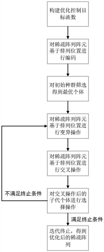
[0036] refer to figure 1 , to further describe the specific steps for realizing the present invention.

[0037] Step 1, construct the optimization control objective function.

[0038] Based on the relationship between the array element distribution of the sparse array antenna and the maximum sidelobe level of the array pattern, the optimal control objective is constructed as follows:

[0039]

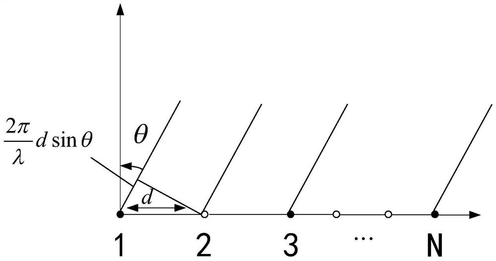
[0040]Among them, MSLL represents the maximum sidelobe level of the sparse array antenna, max represents the maximum value operation, θ represents the angle between the array scanning beam and the array normal, S represents the range of the side lobe of the array pattern, when the array pattern is mainly The lobe width is (-θ 1 , θ 1 ), then -90°≤S≤-θ 1 , and θ 1 ≤S≤90°, || indicates the absolute value operation, N indicates the total number of array ele...


PUM


Abstract

The invention discloses a sparse array optimization method based on an arrangement discrete differential evolution algorithm, and aims to solve the problem that the maximum sidelobe level of an optimization result is slightly high due to binary coding of an infeasible solution and random mutation operation when a genetic algorithm is utilized to optimize a sparse array in the prior art. The method comprises the following steps: constructing an optimization control objective function; coding the sparse array elements based on the arrangement positions; screening the initial population to obtain an optimal individual; carrying out mutation operation on the sparse array elements based on the arrangement positions; performing crossover operation on the sparse array elements based on the arrangement positions; performing selection operation on the offspring individuals after the interlace operation; and terminating iteration, and obtaining an optimized sparse array. When the sparse array is optimized, the sparse array with lower maximum sidelobe level can be obtained, and the efficiency of sparse array optimization is improved while higher resolution is obtained.

Description

technical field [0001] The invention belongs to the technical field of radar signal processing, and further relates to a sparse array optimization method based on an array discrete differential evolution algorithm in the technical field of array design. The present invention can be used for sparse array optimization, realizes the minimum of the maximum sidelobe level as a constraint condition, optimizes and selects several array elements to compress data volume and reduce signal processing pressure. Background technique [0002] Sparse array synthesis is mainly to reduce the maximum sidelobe level of the antenna and improve the performance of the antenna by reasonably planning the working state of the array elements. In order to narrow the antenna beam width and increase the resolution of modern phased array radars, the number of array units is often thousands, and a large number of antenna units and corresponding receiving channels make the cost, volume and complexity of th...

Claims


Application Information

Patent Timeline
Patent Type & Authority Applications(China)
IPC IPC(8): G01S7/41G06N3/12
CPCG01S7/418G06N3/126
Inventor 陈建忠张珂赵雨桐祝森郁张宇
Owner XIDIAN UNIV
Learn More