
Brake pad support following anti-eccentric-wear mechanism and brake device with same

A technology of brake device and brake pad holder, applied in brake wear compensation mechanism, railway braking system, transportation and packaging, etc., can solve the problem of eccentric wear of brake pads and brake discs

Inactive Publication Date: 2021-09-28
BEIJING TIANYOUXINPEI HIGH TECH CO LTD
View PDF0 Cites 0 Cited by
  • Summary
  • Abstract
  • Description
  • Claims
  • Application Information

AI Technical Summary

Problems solved by technology

[0004] Therefore, the technical problem to be solved by the present invention is to overcome the defect that the brake pad anti-eccentric wear device in the prior art will drive the brake pad to deflect when the brake pad is in a free state, resulting in eccentric wear of the brake pad and the brake disc during braking, thereby Provides a brake pad holder following anti-eccentric wear mechanism

Method used


Image

  • Brake pad support following anti-eccentric-wear mechanism and brake device with same
  • Brake pad support following anti-eccentric-wear mechanism and brake device with same
  • Brake pad support following anti-eccentric-wear mechanism and brake device with same

Examples


Embodiment 1

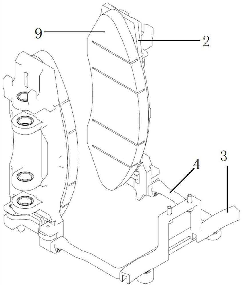
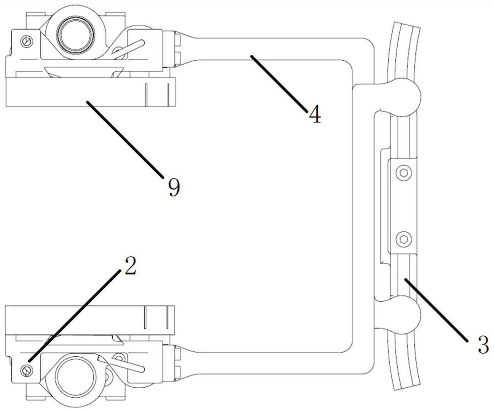
[0036] Such as Figure 1 to Figure 6 As mentioned above, a brake pad holder provided in this embodiment follows the anti-eccentric wear mechanism and is installed between the hanger 1 and a pair of brake pad holders 2, and the pair of brake pad holders 2 are symmetrically installed on both sides of the hanger 1. It includes: a slide rail 3 installed on a hanger 1 and a pair of pull rod bodies 4 .

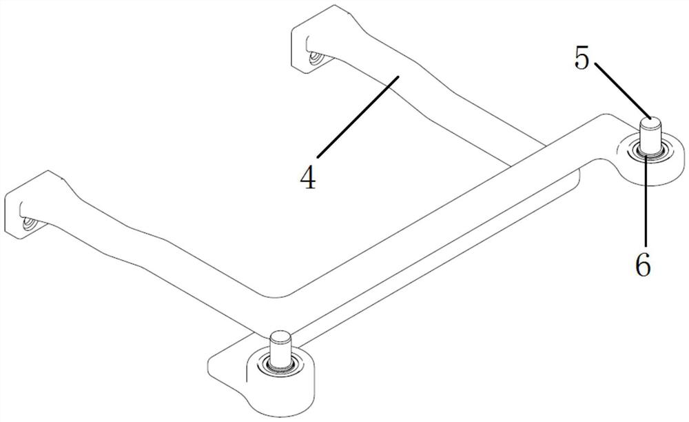
[0037] A pair of tie rod bodies 4 are arranged crosswise, and the tie rod bodies 4 are installed in one-to-one correspondence with the brake pad holder 2. One end of the tie rod body 4 is fixedly installed on the brake pad holder 2, and the other end is vertically installed with a rotating shaft 5, and the rotating shaft 5 is slidably installed on the slide rail 3 Inside and rotatably matched with the slide rail 3, a pair of tie rod bodies 4 are Z-shaped three-section rods, and the middle sections of a pair of tie rod bodies 4 are arranged parallel to each other and abutted against ...

Embodiment 2

[0042] This embodiment provides a braking device, the braking device provided in this embodiment is a brake caliper, which has the anti-eccentric wear mechanism described in Embodiment 1 for the brake pad support. Also includes: a hanger 1, a brake cylinder and a pair of brake pad holders 2.

[0043] The lower side of the hanger 1 is equipped with an intermediate support frame 7, and a pair of brake levers 8 are symmetrically installed on the left and right sides of the intermediate support frame 7, and the brake lever 8 and the intermediate support frame 7 are rotated and matched; At the end of each brake lever 8, a pair of brake pad holders 2 are equipped with a brake pad body 9 on the opposite side. Both ends of the brake cylinder are respectively fixedly connected to one side of a pair of brake levers 8 and one side of the brake pad holder 2 . The brake pad holder follows the guide rail of the anti-eccentric wear mechanism and is installed on the lower side of the middle ...


PUM


Abstract

The invention relates to the technical field of motor car braking devices, in particular to a brake pad support following anti-eccentric-wear mechanism and a braking device with the same. The brake pad support following anti-eccentric-wear mechanism is installed between the hanging bracket and the pair of brake pad supports, and the pair of brake pad supports are symmetrically installed on the two sides of the hanging bracket. The structure comprises a sliding rail arranged on a hanging bracket; a pull rod bodies and the brake pad supports which are installed in a one-to-one correspondence mode, wherein one ends of the pull rod bodies are fixedly installed on the brake pad supports, rotating shafts are vertically installed at the other ends of the pull rod bodies, the rotating shafts are installed in the sliding rails in a sliding mode and matched with the sliding rails in a rotating mode, each pull rod body is a Z-shaped three-section rod, and the middle sections of the pair of pull rod bodies are parallel to each other and abut against each other up and down. By arranging the pair of crossed Z-shaped pull rod bodies, the up-down staggered movement of the brake pad support in the free state is limited by the pull rod bodies, so that when the brake pad support is applied to the brake clamp, eccentric wear between the brake pad and a brake disc is avoided, and the probability of occurrence of conditions such as noise and deformation is reduced.

Description

technical field [0001] The invention relates to the technical field of braking devices for motor vehicles, in particular to a brake pad holder following eccentric wear prevention mechanism and a braking device having the same. Background technique [0002] Four-point hanging brake caliper, the posture of the brake pad holder cannot form a constraint with the bogie. Affected by vibration and impact, the brake pad holder is easy to rotate around the pin axis, and the left and right brake pad holders may not be in harmony with the brake disc. The parallel attitude will eventually cause partial wear of the brake pads, damage the brake disc, reduce the service life of the brake pads, and affect the braking performance. Moreover, the under-constrained state of the free rotation of the brake pad will reduce the stability of the clamp, and it is easy to collide with other related parts, resulting in noise, deformation, and reducing the service life of the brake pad and related parts...

Claims


Application Information

Patent Timeline
Patent Type & Authority Applications(China)
IPC IPC(8): B61H15/00
CPCB61H15/0014
Inventor 吴佩芳吴鹏张舒王春雨马士猛程光华
Owner BEIJING TIANYOUXINPEI HIGH TECH CO LTD
Learn More