Rotary turbulent tube energy-saving water cooling device

A technology for water cooling and turbulent flow tubes, applied in metal processing equipment, metal rolling, manufacturing tools, etc., can solve problems such as shortening service life, turbulent tube wear, and quality reduction, and achieves improved use efficiency, improved yield, Even cooling effect

Active Publication Date: 2017-07-11
湖南天益高技术材料制造有限公司
View PDF2 Cites 0 Cited by
  • Summary
  • Abstract
  • Description
  • Claims
  • Application Information

AI Technical Summary

Problems solved by technology

The general-purpose structure is that the positions of the multiple turbulent tubes installed in the liner are fixed during the cooling process of the rolled material, and cannot be rotated or rotated as required, so that one side (that is, close to the turbulent flow) One side of the turbulence tube) always has contact or friction with the bottom surface of the turbulence tube. After a period of use, the bottom surface of the turbulence tube is worn and needs to be stopped for maintenance and replacement; at the same time, the contact surface of the threaded steel bar cooled by water is also worn in different procedures, reducing quality
Water piercing equipment needs to be improved due to shortened service life, increased maintenance and production costs

Method used


Image

  • Rotary turbulent tube energy-saving water cooling device
  • Rotary turbulent tube energy-saving water cooling device
  • Rotary turbulent tube energy-saving water cooling device

Examples


Embodiment Construction

[0014] The specific implementation manners of the present invention will be further described in detail below in conjunction with the accompanying drawings.

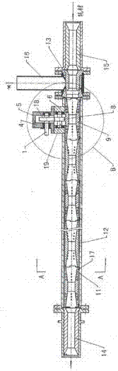
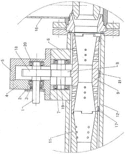
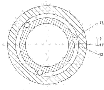
[0015] As shown in the drawings, a rotary turbulent tube energy-saving water-through cooling device according to the present invention includes a driving gear rotating shaft 1, a shaft end cover 2, a rotating shaft Y-shaped sealing ring 3, a driving gear box front cover 4, a driving Gear box 5, driven gear box 6, first bearing 7 (also called driven gear box bearing 7), driven gear 8, driving liner 9, driven liner 11, liner support tube 12, nozzle Seat 13, rolled material tail pipe 14, rolled material inlet pipe 15, water inlet pipe 16, needle roller 17, driving gear 18, driven gear rotating shaft 19, second bearing 20 (also called driving gear box bearing 20) , transmission gear 21 (also can be referred to as transmission gear ring 21), wherein the rolled material tail pipe 14, the rolled material inlet pipe 15, the wate...


PUM


Abstract

The invention discloses an energy-saving rotary turbulent tube through-water cooling device which is characterized in that a driving liner tube and more than one driven liner tube are sequentially mounted in an inner cavity of a liner bracket tube; a transmission gear is processed at the outer wall of the driving liner tube; a driven gear box is mounted at the outer wall of the front end of the liner bracket tube; a driven gear is arranged on a driven gear box rotating shaft mounted in the driven gear box, and is engaged to the transmission gear; a driving gear box and a driving gear box front cover that are connected with each other are arranged at the top end of the driven gear box; the two ends of a driving gear rotating shaft provided with a driving gear engaged to the driven gear are positioned in or penetrate through bearings of the driving gear box and the driving gear box front cover; a rotating shaft Y-shaped sealing ring on the driving gear rotating shaft is inserted into the driving gear box front cover; and a shaft end cover is connected with the driving gear front cover. With the adoption of the device, synchronous rotation of the driving liner tube and the driven liner tubes and rotation of rolled metal can be realized. The service life of the whole device, a heat-exchange rate and a finished product rate of the rolled metal can be increased, and the device has practical values and popularization values.

Description

technical field [0001] The invention relates to a cooling device, in particular to a rotary turbulent tube energy-saving water-through cooling device used in the controlled rolling process of threaded steel bars in industrial and civil buildings to make the threaded steel bars cool evenly and minimize / reduce surface wear. Background technique [0002] At present, after passing through the last pass (K1 pass) in the threaded steel rolling process, the controlled cooling technology is also used to cool the threaded steel bar through water to improve the strength (but increase the brittleness). The process / apparatus used is to pass it through a roll tunnel or liner and allow it to cool. Before the present invention, there was CN203678885U "combined non-steam water-piercing cooling device" and application number 201510196208.X "water-piercing mechanism". The general-purpose structure is that the positions of the multiple turbulent tubes installed in the liner are fixed during t...

Claims


Application Information

Patent Timeline
Patent Type & Authority Patents(China)
IPC IPC(8): B21B45/02
CPCB21B45/0224
Inventor 赵勇颜毅王庄生
Owner 湖南天益高技术材料制造有限公司
Why Eureka
Try Eureka