
Stalk and ear harvesting type corn harvester

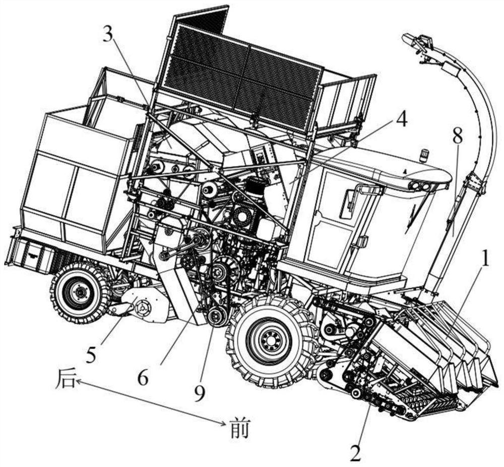
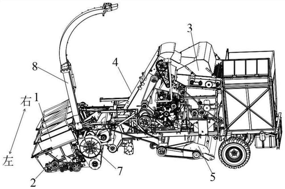
A harvester and corn technology, applied in the direction of harvesters, headers, cutters, etc., can solve the problems of easy bending and failure of the intermediate shaft of the header, uneven distribution of force load, inconvenient maintenance and replacement, etc., to improve the transmission efficiency And the effect of reliability, reasonable layout and space saving

Active Publication Date: 2021-09-28
河北英虎农业机械股份有限公司
View PDF5 Cites 1 Cited by
  • Summary
  • Abstract
  • Description
  • Claims
  • Application Information

AI Technical Summary

Problems solved by technology

[0003] The existing stem and ear harvesting corn harvester generally transmits the power to the upper header, the large elevator, the peeling machine, the lower header, the feeding device, the crusher, and the blower through the multi-stage transmission of the engine. etc. Due to the high number of power transmission stages, the energy loss is large and the product reliability is low
In addition, the existing corn harvester headers are generally unilaterally driven, and only one header shaft is used to drive all moving parts on the entire header. An intermediate shaft not only connects several ear picking units, but also connects two small The elevator is also connected with two auger mechanisms and two straw chopping mechanisms. Due to the uneven force and load distribution, the intermediate shaft of the header is easily bent and fails. Because the header space is small and the structure is compact, it is easy to repair and replace. extremely inconvenient

Method used


Image

  • Stalk and ear harvesting type corn harvester
  • Stalk and ear harvesting type corn harvester
  • Stalk and ear harvesting type corn harvester

Examples


Embodiment Construction

[0084] In order to make the purposes, technical solutions and advantages of the embodiments of the present invention clearer, the technical solutions in the embodiments of the present invention will be clearly and completely described below with reference to the accompanying drawings in the embodiments of the present invention. Obviously, the described embodiments These are some embodiments of the present invention, but not all embodiments. The components of the embodiments of the invention generally described and illustrated in the drawings herein may be arranged and designed in a variety of different configurations.

[0085] Thus, the following detailed description of the embodiments of the invention provided in the accompanying drawings is not intended to limit the scope of the invention as claimed, but is merely representative of selected embodiments of the invention. Based on the embodiments of the present invention, all other embodiments obtained by those of ordinary ski...


PUM


Abstract

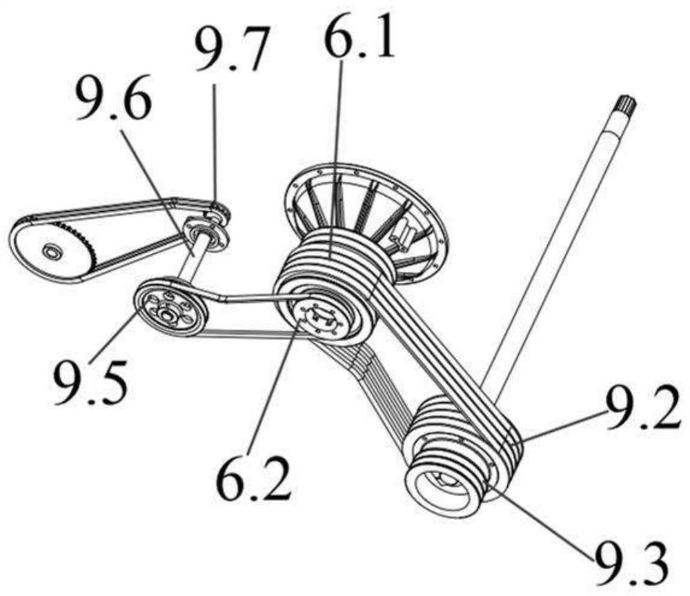
The invention discloses a stalk and ear harvesting type corn harvester which comprises an upper header, a large elevator, a peeling machine, a lower header, a throwing fan, a returning machine and an engine; and a first power main output wheel is arranged on the engine, the first power main output wheel is in transmission connection with a main output shaft through a belt, a peeling machine power transmission wheel is further arranged on the right side of a first main output shaft belt wheel, the peeling machine power transmission wheel is in transmission connection with a peeling machine power shaft, a lower main shaft power transmission wheel and a returning machine power transmission wheel are sequentially arranged at the other end of the main output shaft, the lower main shaft power transmission wheel is in transmission connection with a lower main shaft, the upper header, the lower header and the throwing fan are in transmission connection with the lower main shaft, and the returning machine power transmission wheel is in transmission connection with the returning machine. Power is transmitted to all working units of the corn harvester through one main output shaft, space is saved, arrangement of the transmission system of the whole corn harvester is facilitated, the power transmission stage number is reduced, and the transmission efficiency and reliability are improved.

Description

technical field [0001] The invention relates to the field of corn harvesters, in particular to a stem and ear harvester corn harvester. Background technique [0002] Stem and ear harvester corn harvester generally includes corn harvesting system, straw harvesting system and field return machine. The corn harvesting system includes upper header, large elevator, peeling machine and granary. The upper header is used to pick corn ears. Next, the picked ears are transported to the peeling machine by the large elevator, and the peeled ears are peeled by the peeling machine, and the peeled ears are transported to the granary; The feeding part and the grass bin, the lower cutting platform is used to cut the straw from the root, and the cut straw is transported to the crusher through the feeding device, and the crusher chops the straw, and the chopped grass is thrown through the blower under the action of the throwing fan. The sending part is thrown to the grass bin for recycling; t...

Claims


Application Information

Patent Timeline
Patent Type & Authority Applications(China)
IPC IPC(8): A01D45/02A01D43/08A01D47/00A01D69/06A01D57/00A01D69/08
CPCA01D45/021A01D45/025A01D47/00A01D43/086A01D69/06A01D57/00A01D69/08Y02P60/14
Inventor 李衡李侠其他发明人请求不公开姓名
Owner 河北英虎农业机械股份有限公司
Learn More