Focused ion beam processing apparatus

A processing device and ion beam technology, applied in the direction of discharge tubes, electrical components, circuits, etc., can solve problems such as reduced operating efficiency, residual processing stripes, and increased beam diameter, and achieve the effect of improving operating efficiency and improving cross-sectional shape

Pending Publication Date: 2021-09-24
HITACHI HIGH TECH SCI CORP
View PDF1 Cites 0 Cited by
  • Summary
  • Abstract
  • Description
  • Claims
  • Application Information

AI Technical Summary

Problems solved by technology

[0008] However, in the case of the above-mentioned converging mode, the beam diameter increases at a large current, so there are problems in that rounded corners are generated near the upper surface of the sample in the cross section, or in substances with different sputtering efficiencies including devices, etc. In the sample, processing stripes or steps remain
On the other hand, if Figure 12 As shown, the required section is in the form of a slope 200s connected to the section 200c, and unnecessarily excavating deeper than the slope 200s will result in a decrease in work efficiency
[0023] In addition, since the sputtering product of the portion obtained by etching unnecessarily adheres to the cross section, the amount of finishing work for obtaining a sharp cross section increases, which also leads to a decrease in work efficiency.
[0024] In addition, in the case of the technique of Patent Document 3, since no projection lens is used between the baffle and the sample to project toward the sample in the shape of the opening of the baffle, the beam shape is as small as several μm at most, Unable to generate shaped beams of a size that can uniformly process cross-sections

Method used


Image

  • Focused ion beam processing apparatus
  • Focused ion beam processing apparatus
  • Focused ion beam processing apparatus

Examples


Embodiment Construction

[0073] Hereinafter, embodiments of the present invention will be described with reference to the drawings.

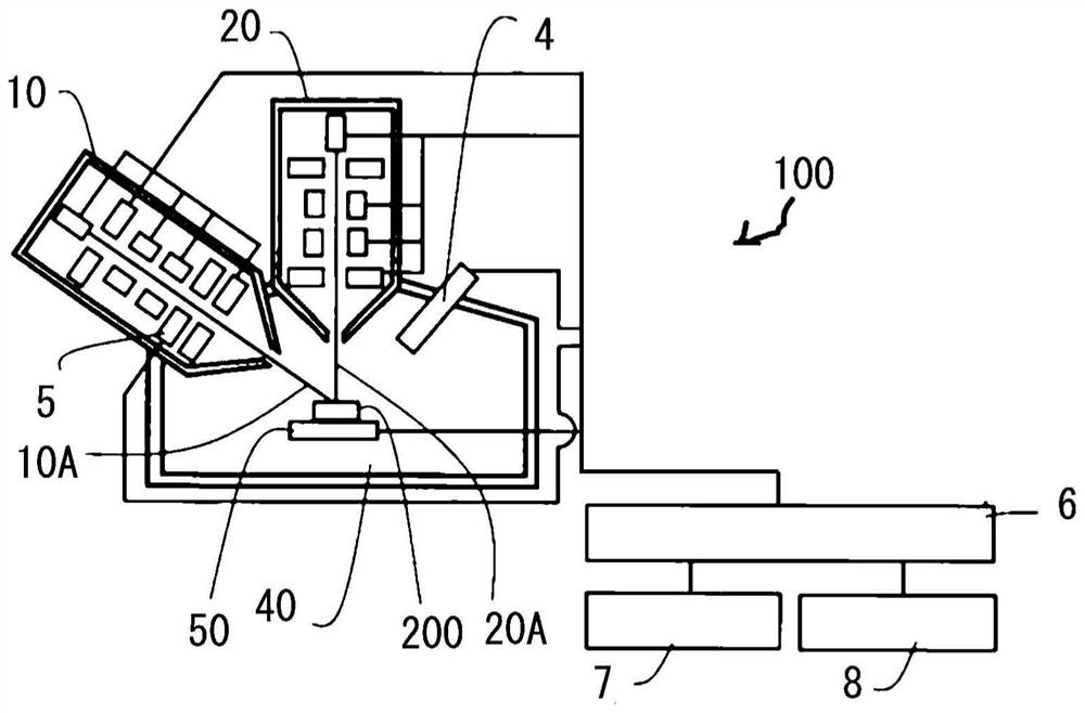
[0074] figure 1 It is a block diagram showing the overall configuration of the convergent ion beam processing apparatus 100 according to the embodiment of the present invention. exist figure 1 Among them, the convergent ion beam processing apparatus 100 has an electron beam column (SEM column) 10, a convergent ion beam column (FIB column) 20, secondary electron detectors 4, 5, a control unit 6, a display unit 7, an input The unit 8 and the sample stage 50 can process the sample 200 arranged on the sample stage 50 with a converged ion beam, and observe it with a SEM.

[0075] Also, while in figure 1 In the embodiment, the FIB column 20 is arranged vertically, and the SEM column 10 is arranged inclined at a predetermined angle with respect to the vertical, but the present invention is not limited thereto.

[0076] Some or all of the components of the converged ion ...


PUM


Abstract

The present disclosure is directed to providing a focused ion beam processing apparatus capable of improving a shape of a cross-section when cross-section processing is performed using a focused ion beam, and improving operation efficiency. The focused ion beam processing apparatus (100) includes: an ion source (21); a sample stage (50) holding a sample; a condenser lens (22); an aperture (24) having having a slit (24) with at least one side in a straight line shape; a projection lens (28) placed in a beam path between the aperture and the sample stage; the sample is machined with a section; in a transfer mode, by Kohler illumination, with an applied voltage of the condenser lens when the focused ion beam (20A) is focused on a main surface of the projection lens scaled to be 100, the applied voltage is set to be less than 100 and greater than or equal to 80; a position of the aperture is set such that the focused ion beam is masked by the aperture with the one side of the aperture at a distance greater than 0 [,u]m and equal to or less than 500 [mu]m from a center of the focused ion beam, so that the shape of the slit is transferred onto the sample.

Description

technical field [0001] The present invention relates to a convergent ion beam processing device for processing the cross section of a sample. Background technique [0002] Conventionally, a convergent ion beam processing apparatus has been used to process a cross-section of a sample and observe the cross-section. [0003] Such as Figure 12 Section machining is performed as shown. First, a convergent ion beam 20A is irradiated perpendicularly to the surface 200 a of the sample 200 . Then, the irradiation position of the convergent ion beam 20A is scanned, and a cross section 200c perpendicular to the surface 200a of the sample 200 (parallel to the irradiation direction of the convergent ion beam 20A) is excavated. [0004] However, there is an angle between the electron beam 10A and the converging ion beam 20A of the SEM column observing the section 200c after section processing, so it is not necessary to excavate as deeply as the vicinity of the section for the part separ...

Claims


Application Information

Patent Timeline
Patent Type & Authority Applications(China)
IPC IPC(8): H01J37/09H01J37/12H01J37/305
CPCH01J37/09H01J37/12H01J37/3056H01J2237/026H01J2237/12H01J2237/31H01J37/3007H01J2237/045H01J2237/30477H01J2237/31745H01J37/10H01J37/20H01J37/305H01J37/08H01J37/3175H01J2237/31788H01J37/21
Inventor 大庭弘杉山安彦中川良知永原幸儿
Owner HITACHI HIGH TECH SCI CORP
Why Eureka
Try Eureka