Focused ion beam processing apparatus

a processing apparatus and focused ion beam technology, applied in the direction of electrical apparatus, electric discharge tubes, basic electric elements, etc., can solve the problems of reducing operation efficiency, increasing the processing cost of acquiring a sharp cross-section, and low operation efficiency, so as to improve the shape of the cross-section, improve operation efficiency, and improve the effect of operation efficiency

Active Publication Date: 2021-09-23
HITACHI HIGH TECH SCI CORP
View PDF9 Cites 0 Cited by
  • Summary
  • Abstract
  • Description
  • Claims
  • Application Information

AI Technical Summary

Benefits of technology

The patent text describes an improved focused ion beam processing apparatus that can improve the shape of a cross-section during processing, and also increase operation efficiency. This means that the apparatus can perform cross-section processing faster and with greater precision using a focused ion beam.

Problems solved by technology

Therefore, generally, operation efficiency is low.
This decreases operation efficiency.
In addition, sputter products of the unnecessarily etched part adhere to the cross-section, and thus the amount of finish processing for acquiring a sharp cross-section increases, which decreases operation efficiency.

Method used


Image

  • Focused ion beam processing apparatus
  • Focused ion beam processing apparatus
  • Focused ion beam processing apparatus

Examples


Embodiment Construction

[0060]Hereinafter, an embodiment of the present disclosure will be described with reference to the accompanying drawings.

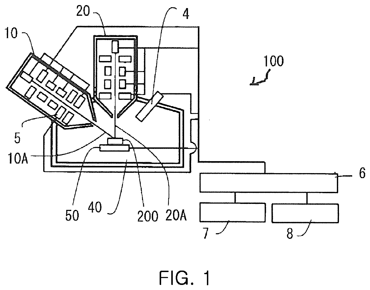
[0061]FIG. 1 is a diagram showing an overall configuration of a focused ion beam processing apparatus 100 according to an embodiment of the present disclosure. In FIG. 1, the focused ion beam processing apparatus 100 includes an electron beam column (SEM column) 10, a focused ion beam column (FIB column) 20, secondary electron detectors 4 and 5, a control means 6, a display unit 7, an input means 8, and a sample stage 50. A sample 200 placed on the sample stage 50 is processed by a focused ion beam and observation is performed using an SEM.

[0062]In addition, in FIG. 1, the FIB column 20 is placed to be vertical, and the SEM column 10 is placed at a predetermined angle from the vertical, but no limitation thereto is imposed.

[0063]A part or all of the elements of the focused ion beam processing apparatus 100 are provided inside a vacuum chamber 40, and the internal ...


PUM


Abstract

Provided is a focused ion beam processing apparatus including: an ion source; a sample stage a condenser lens; an aperture having a slit in a straight line shape; a projection lens and the sample stage, wherein, in a transfer mode, by Köhler illumination, with an applied voltage of the condenser lens when a focused ion beam is focused on a main surface of the projection lens scaled to be 100, the applied voltage is set to be less than 100 and greater than or equal to 80; a position of the aperture is set such that the focused ion beam is masked by the aperture with the one side of the aperture at a distance greater than 0 μm and equal to or less than 500 μm from a center of the focused ion beam; and the shape of the slit is transferred onto the sample.

Description

CROSS REFERENCE TO RELATED APPLICATION(S)[0001]This application claims the benefit of Japanese Patent Application No. 2020-050997, filed Mar. 23 2020, which is hereby incorporated by reference in its entirety into this application.BACKGROUND OF THE INVENTION1. Technical Field[0002]The present disclosure relates to a focused ion beam processing apparatus performing cross-section processing of a sample.2. Description of the Related Art[0003]Conventionally, a focused ion beam processing apparatus is used to perform cross-section processing of a sample and the cross-section is observed.[0004]Cross-section processing is performed as shown in FIG. 12. First, being perpendicular to a surface 200a of a sample 200, a focused ion beam 20A is emitted. Then, by scanning an irradiation position of a focused ion beam 20A, a cross-section 200c (parallel to the irradiation direction of the focused ion beam 20A) perpendicular to the surface 200a of the sample 200 is etched.[0005]However, there is an...

Claims


Application Information

Patent Timeline
Patent Type & Authority Applications(United States)
IPC IPC(8): H01J37/12H01J37/20H01J37/09H01J37/317H01J37/08H01J37/21
CPCH01J37/12H01J37/20H01J37/09H01J2237/31788H01J37/08H01J37/21H01J37/3175H01J37/3056H01J2237/026H01J2237/12H01J2237/31H01J37/3007H01J2237/045H01J2237/30477H01J2237/31745H01J37/10H01J37/305
Inventor OBA, HIROSHISUGIYAMA, YASUHIKONAKAGAWA, YOSHITOMONAGAHARA, KOJI
Owner HITACHI HIGH TECH SCI CORP
Why Eureka
Try Eureka