Manufacturing method of wind tunnel heater with special-shaped air pipe

A heater and air pipe technology, applied in the field of wind tunnel heater preparation with special-shaped air pipes, can solve problems such as difficult to ensure brazing gap, uncontrollable assembly quality, and affecting brazing quality, so as to reduce processing costs and increase brazing Effect of area and material saving

Active Publication Date: 2021-09-24
XIAN YUANHANG VACUUM BRAZING TECH
View PDF4 Cites 2 Cited by
  • Summary
  • Abstract
  • Description
  • Claims
  • Application Information

AI Technical Summary

Problems solved by technology

Because the second partition is a high-strength and high-conductivity copper alloy, and the rest are austenitic stainless steel, the physical and chemical metallurgical properties of the two materials are quite different, and welding is more difficult; in addition, there are special-shaped air tubes on the second partition During assembly, the fit between the special-shaped air pipe, the first partition and the shell is invisible, the assembly quality is uncontrollable, and the solder is difficult to preset; the joints involved in the wind tunnel heater containing the special-shaped air pipe include the shell, the first partition It is difficult to ensure the brazing gap by direct processing at the plate, the second partition, the liquid nozzle, and the gas pipe, which affects the brazing quality and is low in efficiency

Method used


Image

  • Manufacturing method of wind tunnel heater with special-shaped air pipe
  • Manufacturing method of wind tunnel heater with special-shaped air pipe
  • Manufacturing method of wind tunnel heater with special-shaped air pipe

Examples


preparation example Construction

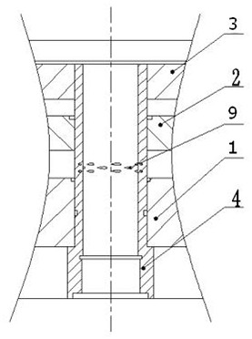
[0044] see Figure 5~Figure 7 , a method for preparing a wind tunnel heater containing a special-shaped air pipe, comprising the following steps:

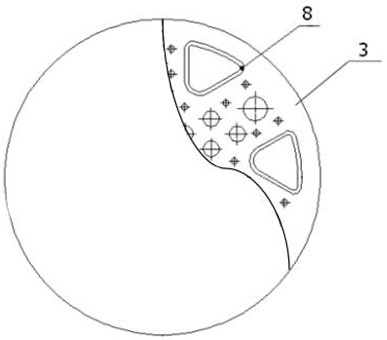
[0045] (1) Processing fluid nozzle 4, special-shaped air pipe 8, air pipe 5 and shell 1, the assembly positions of liquid nozzle 4, special-shaped air pipe 8, and air pipe 5 are reserved on shell 1;

[0046] (2) After cleaning the liquid nozzle 4, the special-shaped air pipe 8, the air pipe 5 and the shell 1, assemble the liquid nozzle 4, the special-shaped air pipe 8, and the air pipe 5 in the assembly position of the shell 1 in sequence, and then align them through the burr positioning;

[0047] (3) Evenly apply paste-like solder on the liquid nozzle 4, special-shaped air pipe 8, air pipe 5 and shell 1 to be brazed; process the first partition 2, and set up on the first partition 2 for soldering A collecting tank 13 for flow diversion;

[0048](4) Paste the adhesive tape solder on the surface to be brazed of the first partition...


PUM

PropertyMeasurementUnit
thicknessaaaaaaaaaa

Abstract

The invention discloses a manufacturing method of a wind tunnel heater with a special-shaped air pipe. The manufacturing method comprises the following operation steps: a liquid nozzle, the special-shaped air pipe, an air pipe and a shell are machined; the liquid nozzle, the special-shaped air pipe and the air pipe are sequentially assembled at the assembling positions of the shell; a first partition plate is machined, and a flow collecting groove used for conducting flow dividing on brazing filler metal is formed in the first partition plate; the first partition plate penetrates through the liquid nozzle, the special-shaped air pipe and the air pipe and is assembled on the shell to obtain an assembly component; the assembly component is placed in a vacuum brazing furnace to be subjected to vacuum brazing to obtain a primarily brazed component; a second partition plate is machined, the second partition plate is assembled on the first partition plate and the shell, and then a special-shaped air pipe reinforcing ring, an air pipe reinforcing ring and a liquid nozzle reinforcing ring are assembled on the second partition plate; after assembling is completed, a cover plate groove is machined, a cover plate is assembled into the cover plate groove to obtain a heater component; and the heater component is subjected to vacuum brazing. By adjusting the brazing structure, the welding difficulty is reduced, and the product quality is guaranteed.

Description

technical field [0001] The invention belongs to the technical field of aerospace precision manufacturing, and relates to a preparation method of a wind tunnel heater with a special-shaped air pipe. Background technique [0002] A schematic diagram of a wind tunnel heater with a special-shaped trachea figure 1 As shown, the heater is composed of a shell, a first partition, a second partition, an air pipe and a liquid nozzle, wherein the second partition is a high-strength and high-conductivity copper alloy, and the rest are all austenitic stainless steel. The heater has a "three-plate, two-cavity" structure, and the parts are vacuum brazed to form a fuel chamber and a water-cooling chamber. The fuel chamber and the water-cooling chamber must withstand a pressure of 4MPa alone and cannot be connected in series. Because the second partition is a high-strength and high-conductivity copper alloy, and the rest are austenitic stainless steel, the physical and chemical metallurgica...

Claims


Application Information

Patent Timeline
Patent Type & Authority Applications(China)
IPC IPC(8): B23K1/008B23K1/20G01N3/12G01M3/02G01N21/88
CPCB23K1/008B23K1/0008B23K1/20B23K1/206G01N3/12G01M3/02G01N21/8803
Inventor 康路路任军李淑芳王程成吉小岗
Owner XIAN YUANHANG VACUUM BRAZING TECH
Why Eureka
Try Eureka