A fully automatic monitoring and control centralized lubrication system for traveling wheels of a crane

Active Publication Date: 2021-11-23
HENAN WEIHUA HEAVY MACHINE
View PDF1 Cites 0 Cited by
  • Summary
  • Abstract
  • Description
  • Claims
  • Application Information

AI Technical Summary

Problems solved by technology

For the problem of lubricating and refueling the wheels of the crane walking system, for a long time, it is mainly through manual regular inspection of the lubrication system, and then manually or electrically adding butter to the system, and then supplying oil to each wheel through the oil distributor to maintain its walking system For the normal operation of the crane, the centralized lubrication method of the existing crane travel system is single and the structure is complex. The vibration generated by the crane operation will affect the components of the lubrication system, which will cause leakage, which will cause dry friction in the operating system and cause premature damage to the operating components; In addition, the oil supply cycle and the amount of grease supplied to each lubrication point are different, and manual regular inspection and refueling require frequent operations, time-consuming and labor-intensive
[0003] A Chinese invention with the authorized notification number CN103573999B discloses a crane walking wheel open gear lubrication system and a crane including it. The oil tank, the other end of the oil pipe is connected to the solenoid valve, the solenoid valve is used to control the opening and closing of the lubrication system, which depends on the installation height of the oil tank, through the action of gravity, and then through the solenoid valve and flow regulating valve to drip oil on the open gear Lubrication, but it still needs to manually detect the operation of the open gear or open the solenoid valve depending on the length of time, lack of automatic recognition for oil replenishment operation

Method used


Image

  • A fully automatic monitoring and control centralized lubrication system for traveling wheels of a crane
  • A fully automatic monitoring and control centralized lubrication system for traveling wheels of a crane
  • A fully automatic monitoring and control centralized lubrication system for traveling wheels of a crane

Examples


Embodiment Construction

[0048] The technical solutions of the present invention will be described below in conjunction with the accompanying drawings in the embodiments of the present invention. In the description, it should be understood ", "Right" and other indicated orientations or positional relationships are only corresponding to the drawings of the present invention. In order to facilitate the description of the present invention, they do not indicate or imply that the referred device or element must have a specific orientation:

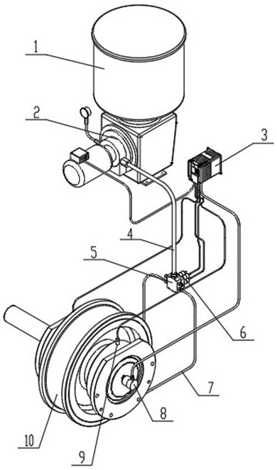
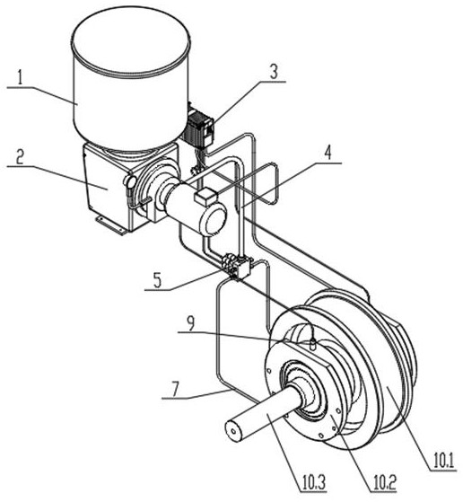
[0049] see Figure 1-18 , the present invention provides a technical solution: a fully automatic monitoring and control centralized lubrication system for the traveling wheels of a crane, including an oil tank 1, an electric grease pump 2, a controller 3, an oil distributor 5, an electromagnetic control valve 6 and a plurality of traveling wheels Unit 10; the electric grease pump 2 communicates with the oil tank 1, and the electric grease pump 2 communicates with the ...


PUM


Abstract

The invention discloses a fully automatic monitoring and control centralized lubrication system for traveling wheels of a crane, which comprises an oil tank, an electric grease pump, a controller, an oil distributor, an electromagnetic control valve and a plurality of traveling wheel units; the electric grease pump and the oil tank connected, and the electric grease pump communicates with the oil distributor through the oil supply main pipe, and each of the walking wheel units communicates with the corresponding oil outlet of the oil distributor through two oil supply branch pipes; the oil distributor is equipped with multiple independent An electromagnetic control valve that controls the oil supply opening or closing of its corresponding oil outlet. The invention is easy to operate, can monitor the lubrication status of each wheel lubrication point in real time, thereby controlling the lubrication system to refuel or cut off the oil, realizes the automatic monitoring control and lubrication of the walking system, improves the service life of the running parts, and minimizes the Grease leakage, reducing the maintenance cost of the system later.

Description

technical field [0001] The invention relates to the technical field of cranes, in particular to a fully automatic monitoring and control centralized lubrication system for traveling wheels of a crane. Background technique [0002] Lubrication system refers to the general term for a series of grease supply, grease discharge and its accessories that supply lubricant to the lubrication part. For the problem of lubricating and refueling the wheels of the crane walking system, for a long time, it is mainly through manual regular inspection of the lubrication system, and then manually or electrically adding butter to the system, and then supplying oil to each wheel through the oil distributor to maintain its walking system For the normal operation of the crane, the centralized lubrication method of the existing crane travel system is single and the structure is complex. The vibration generated by the crane operation will affect the components of the lubrication system, which will ...

Claims


Application Information

Patent Timeline
Patent Type & Authority Patents(China)
IPC IPC(8): F16C33/66F16N7/38F16N25/00F16N23/00F16N21/00F16N21/06F16N29/02F16K5/04F16K31/40B66C9/08
CPCF16C33/6625F16N7/385F16N25/00F16N23/00F16N21/00F16N21/06F16N29/02F16K5/0442F16K31/40B66C9/08F16N2210/14F16N2250/18F16N2280/02F16N2270/70F16N2270/20
Inventor 刘永刚王玉金刘新波刘富利聂雨萱张旭东梁雪艳王斌刘光辉
Owner HENAN WEIHUA HEAVY MACHINE
Why Eureka
Try Eureka