Low-carbon-source sewage treatment device and treatment method

A technology of sewage treatment device and sewage treatment method, which is applied in water/sewage treatment, biological treatment device, biological water/sewage treatment, etc., can solve the difficulty of treatment and disposal, the requirements of numerical control and operating conditions are relatively high, and it is impossible to take into account the denitrification at the same time. and phosphorus removal, to achieve the effect of strengthening the effect of nitrogen and phosphorus removal, reducing the impact and increasing the output.

Inactive Publication Date: 2021-09-17
SUN YAT SEN UNIV +1
View PDF4 Cites 0 Cited by
  • Summary
  • Abstract
  • Description
  • Claims
  • Application Information

AI Technical Summary

Problems solved by technology

[0002] In the field of sewage treatment, the current sewage treatment process mainly faces the following three problems: 1) The cost of excess sludge treatment and disposal is high, and the treatment and disposal are difficult; 2) The low-carbon source characteristics of influent water often cannot be used in the process of nitrogen and phosphorus removal. At the same time, the requirements of denitrification and phosphorus removal are taken into account; 3) From the perspective of resource / energy recovery water plants, the recovery of carbon, nitrogen and phosphorus is also a problem that needs to be considered
These new processes have relatively high requirements on numerical control and operating conditions, and their mechanism, process design and influencing factors are still in the exploratory stage, and cannot be effectively promoted and popularized in the short term.

Method used


Image

  • Low-carbon-source sewage treatment device and treatment method
  • Low-carbon-source sewage treatment device and treatment method
  • Low-carbon-source sewage treatment device and treatment method

Examples


Embodiment 1

[0068] This embodiment provides a low-carbon source sewage treatment device 10 .

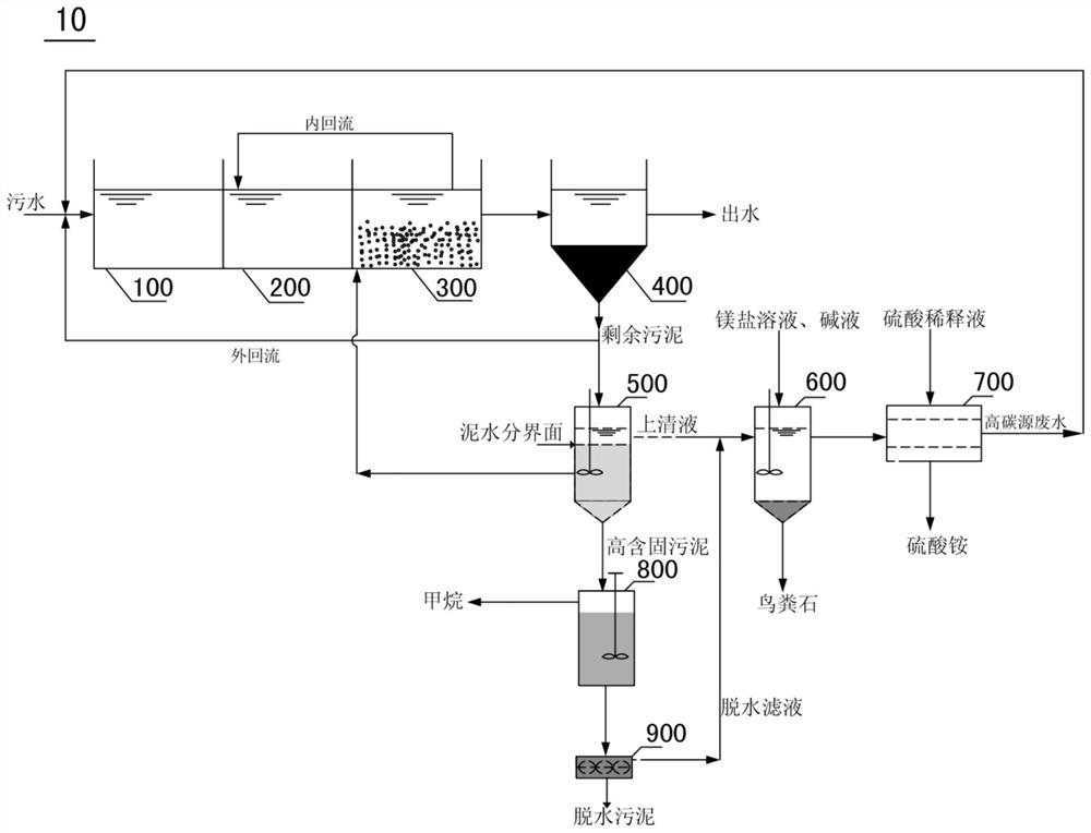
[0069] A low-carbon source sewage treatment device 10, including anaerobic tank 100, anoxic tank 200, aeration tank 300, secondary settling tank 400, biological selection mud-water separation tank 500, phosphorus recovery tank 600, ammonia nitrogen recovery tank 700, high content Solid anaerobic fermentation tank 800 and muddy water dehydration mechanism 900.

[0070] The anaerobic tank 100, the anoxic tank 200, the aeration tank 300, the secondary sedimentation tank 400, the biological selection mud-water separation tank 500, the phosphorus recovery tank 600 and the ammonia nitrogen recovery tank 700 are sequentially connected along the sewage flow direction. The high-solid anaerobic fermentation tank 800 is connected with the biological selection mud-water separation tank 500 . The muddy water dehydration mechanism 900 is connected with the high-solid anaerobic fermentation tank 800 .

[007...

Embodiment 2

[0080] This embodiment provides a low-carbon source influent sewage treatment method with the characteristics of sludge reduction and carbon, nitrogen and phosphorus resource recovery. The method uses the low-carbon source sewage treatment device 10 in Example 1.

[0081] A low-carbon source influent sewage treatment method with the characteristics of sludge reduction and carbon, nitrogen and phosphorus resource recovery, comprising the following steps:

[0082] Sewage treatment stage: urban sewage from low-carbon sources enters anaerobic tank 100, anoxic tank 200, aeration tank 300 and secondary sedimentation tank 400 for anaerobic treatment, anoxic treatment, aeration treatment and sedimentation treatment respectively to control anaerobic The hydraulic retention times in the tank 100, the anoxic tank 200 and the aeration tank 300 are 2 hours, 2 hours and 6 hours respectively. The sludge internal reflux ratio is 80% to 120%, and the sludge external reflux ratio is 10% to 50%...

Embodiment 3

[0089] In this example, the low-carbon source influent sewage treatment method with the characteristics of sludge reduction and carbon, nitrogen and phosphorus resource recovery in Example 2 is used to treat urban sewage to verify the effect of sludge reduction.

[0090] This embodiment sets the traditional A 2 / O process was used as the control group. In this embodiment 3, the residence time of the biological selection mud-water separation tank 500 is 5 days.

[0091] Compared with the control group, the apparent yield of sludge obtained by the sewage treatment method in Example 3 is 0.256KG-MLSS / KG-COD, and the apparent yield of sludge in the control group is 0.383KG-MLSS / KG-COD , the modified A2 / O process, it can be seen that the sludge growth rate in Example 3 was significantly lower than that of the control group, and a reduction effect of 33% was obtained.

[0092] Sludge apparent yield (Yobs) is an important index to measure the sludge reduction effect of the system. ...


PUM


Abstract

The invention discloses a low-carbon-source sewage treatment device and a treatment method. The treatment device comprises an anaerobic tank, an anoxic tank, an aeration tank, a secondary sedimentation tank, a biological selection mud-water separation tank, a phosphorus recovery tank, an ammonia nitrogen recovery tank, a high-solid-content anaerobic fermentation tank and a mud-water dehydration mechanism, the anaerobic tank, the anoxic tank, the aeration tank, the secondary sedimentation tank, the biological selection mud-water separation tank, the phosphorus recovery tank and the ammonia nitrogen recovery tank are sequentially connected along the flowing direction of sewage, and the high-solid anaerobic fermentation tank is connected with the biological selection mud-water separation tank. And the mud-water dehydration mechanism is connected with the high-solid-content anaerobic fermentation tank. The treatment device has the functions of carbon, nitrogen and phosphorus resource recovery and sludge reduction while ensuring that the sewage quality reaches the standard, the sludge source reduction is 33%, the phosphorus recovery rate reaches 92% or above, and the ammonia nitrogen recovery rate reaches 92%.

Description

technical field [0001] The invention relates to the technical field of sewage treatment, in particular to a low-carbon source sewage treatment device and treatment method. Background technique [0002] In the field of sewage treatment, the current sewage treatment process mainly faces the following three problems: 1) The cost of excess sludge treatment and disposal is high, and the treatment and disposal are difficult; 2) The low-carbon source characteristics of influent water often cannot be used in the process of nitrogen and phosphorus removal. At the same time, the requirements of denitrification and phosphorus removal are taken into account; 3) From the perspective of resource / energy recovery water plants, the recovery of carbon, nitrogen and phosphorus is also a problem that needs to be considered. In recent years, new processes for biological phosphorus and nitrogen removal have gradually emerged, such as the improved A 2 / O process, BICT process, etc., or denitrific...

Claims


Application Information

Patent Timeline
Patent Type & Authority Applications(China)
IPC IPC(8): C02F9/14C02F101/16C02F101/10
CPCC02F9/00C02F3/30C02F1/52C02F1/58C02F1/586C02F11/04C02F11/121C02F2101/16C02F2101/105C02F2203/006C02F2303/06C02F2301/046C02F2303/14
Inventor 邓欢忠孙连鹏曹宇安廖嘉俊吴志城梁子豪刘莹叶从容周琳王昭凯于春霞
Owner SUN YAT SEN UNIV
Why Eureka
Try Eureka