
Intelligent welding machine using rod-shaped welding wires

A welding machine and welding wire technology, which is applied in welding equipment, welding accessories, arc welding equipment, etc., can solve the problems of unable to ensure uniform wire feeding, unable to automatically adjust the angle of welding wire, welding wire wear and bending, etc., so as to avoid welding wire conveying failure Uniformity, stable welding wire delivery, avoiding wear and tear

Active Publication Date: 2021-09-17
广州市顺卓建设工程有限公司
View PDF8 Cites 0 Cited by
  • Summary
  • Abstract
  • Description
  • Claims
  • Application Information

AI Technical Summary

Problems solved by technology

[0002] When the operator needs to use rod-shaped welding wire for welding, he needs to align the welding wire with the workpiece and cooperate with the welding head for welding. The current welding operation of welding wire is basically performed manually by holding the welding wire in one hand and welding torch in the other. Not only increases the human labor, but also easily hurts oneself
[0003] When the welding wire is in the wire feeding stage, the current wire feeding mechanism cannot adjust the wire feeding speed. When welding the workpiece, if the wire feeding speed is too fast or too slow, it will lead to poor welding, and it is easy to cause the welding wire to wear and bend. For the automatic feeding of welding wire, the existing wire feeding mechanism cannot ensure that the wire is fed evenly without damaging the welding wire, and it is also unable to automatically adjust the angle of the welding wire, which will easily affect the welding of the workpiece

Method used


Image

  • Intelligent welding machine using rod-shaped welding wires
  • Intelligent welding machine using rod-shaped welding wires
  • Intelligent welding machine using rod-shaped welding wires

Examples


Embodiment Construction

[0049] The following description serves to disclose the present invention to enable those skilled in the art to carry out the present invention. The preferred embodiments described below are only examples, and those skilled in the art can devise other obvious variations.

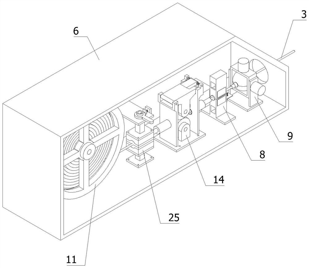
[0050] In order to solve the technical problem of how to adjust the feeding speed of the welding wire 3 and the welding angle, such as Figure 1-Figure 3 As shown, the following technical solutions are provided:

[0051] include:

[0052] Industrial robot 1;

[0053] The wire feeding device 2 is used to pre-feed the welding wire 3 to the welding position of the workpiece, and is arranged on the industrial robot 1;

[0054] The welding table 4 is used to place the workpiece and is arranged on the side of the wire feeding device 2;

[0055] The welding robot 5 is arranged on the side of the welding table 4;

[0056] The wire feeding device 2 includes: an adjustable wire feeding assembly and an angle adjus...


PUM


Abstract

The invention relates to the technical field of welding, in particular to an intelligent welding machine using rod-shaped welding wires. The machine comprises an industrial robot, a wire feeding device, a welding table and a welding robot; the welding table is used for placing workpieces and is arranged beside the wire feeding device; the wire feeding device comprises an adjustable wire feeding assembly and an angle adjusting assembly; the adjustable wire feeding assembly is used for adjusting the wire feeding speed of the welding wires according to the welding efficiency of the workpieces and comprises a shell, a wire rolling mechanism and a wire feeding speed sensing mechanism; a displacement sensor used for sensing the conveying amount of the welding wires is arranged on the wire feeding speed sensing mechanism; and the wire rolling mechanism, the wire feeding speed sensing mechanism and the angle adjusting assembly are all located on the unified horizontal line. through cooperation of the wire rolling mechanism and the wire feeding speed sensing mechanism, the welding wire conveying speed can be conveniently adjusted according to the welding condition, and the angles of the welding wires can be freely adjusted through the angle adjusting assembly during welding, so that the welding efficiency and the welding precision are improved.

Description

technical field [0001] The invention relates to the field of welding technology, in particular to an intelligent welding machine using rod-shaped welding wire. Background technique [0002] When the operator needs to use rod-shaped welding wire for welding, he needs to align the welding wire with the workpiece and cooperate with the welding head for welding. The current welding operation of welding wire is basically performed manually by holding the welding wire in one hand and welding torch in the other. Not only increases the human labor, but also easily hurts oneself. [0003] When the welding wire is in the wire feeding stage, the current wire feeding mechanism cannot adjust the wire feeding speed. When welding the workpiece, if the wire feeding speed is too fast or too slow, it will lead to poor welding, and it is easy to cause the welding wire to wear and bend. For the automatic feeding of welding wire, the existing wire feeding mechanism cannot ensure that the wire i...

Claims


Application Information

Patent Timeline
IPC IPC(8): B23K9/133B23K9/32
CPCB23K9/133B23K9/32
Inventor 程联涛
Owner 广州市顺卓建设工程有限公司
Learn More