
Multi-objective optimization method, device and terminal for cooling, heating and power cogeneration system

A multi-objective optimization, combined cooling, heating and power technology, applied in the field of power system, can solve problems such as equipment can not be fully utilized, increase the difficulty of optimization solution, increase investment cost, etc., to reduce random clustering, reduce emissions, reduce The effect of running costs

Active Publication Date: 2022-05-03
STATE GRID HEBEI ELECTRIC POWER CO LTD +3
View PDF0 Cites 0 Cited by
  • Summary
  • Abstract
  • Description
  • Claims
  • Application Information

AI Technical Summary

Problems solved by technology

At present, the design scheme of the combined cooling, heating and power system still mostly sets the capacity of each equipment according to the peak load, which makes the capacity of the completed combined cooling, heating and power system equipment unable to be fully utilized, increasing investment costs, and poor economy. Operational optimization of combined cooling, heating and power systems is required
[0004] However, the inventors of this application found that with the development of distributed power generation technology, wind power, photovoltaic and other equipment are gradually being introduced into the CCHP system, making the system structure more complicated
Moreover, in order to suppress the impact of output fluctuations of renewable energy power generation devices on the system, energy storage equipment is usually introduced into the system, which further increases the difficulty of the optimization solution

Method used


Image

  • Multi-objective optimization method, device and terminal for cooling, heating and power cogeneration system
  • Multi-objective optimization method, device and terminal for cooling, heating and power cogeneration system
  • Multi-objective optimization method, device and terminal for cooling, heating and power cogeneration system

Examples


Embodiment Construction

[0029] In the following description, specific details such as specific system structures and technologies are presented for the purpose of illustration rather than limitation, so as to thoroughly understand the embodiments of the present invention. It will be apparent, however, to one skilled in the art that the invention may be practiced in other embodiments without these specific details. In other instances, detailed descriptions of well-known systems, devices, circuits, and methods are omitted so as not to obscure the description of the present invention with unnecessary detail.

[0030] In order to illustrate the technical solutions of the present invention, specific examples are used below to illustrate.

[0031] With the rapid growth of the world economy, countries all over the world consume more and more energy. In order to find a clean energy supply method with high energy efficiency, the waste heat generated during the generator power generation process is used to pro...


PUM


Abstract

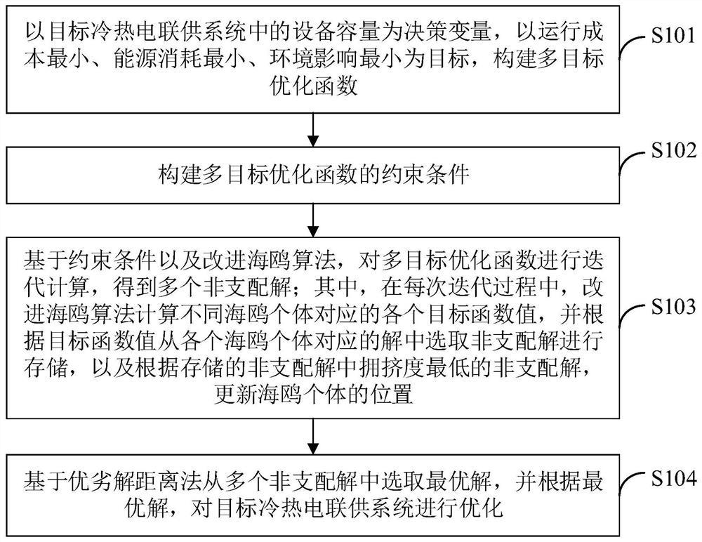
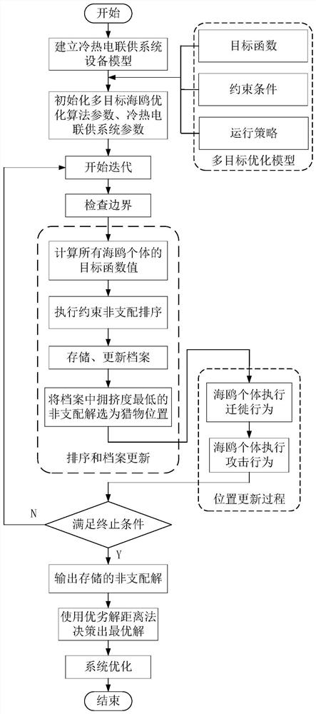
The present invention is applicable to the technical field of electric power systems, and in particular relates to a multi-objective optimization method, device and terminal of a combined cooling, heating and power supply system. The method includes: constructing a multi-objective optimization function and its constraint conditions; , iteratively calculates the multi-objective optimization function to obtain multiple non-dominated solutions; in each iteration process, the improved seagull algorithm calculates the values ​​of each objective function corresponding to different individual seagulls, and according to the value of the objective function, the solutions corresponding to each individual seagull Select the non-dominated solution for storage, and update the position of the seagull individual according to the non-dominated solution with the lowest degree of crowding among the stored non-dominated solutions; select the optimal solution from multiple non-dominated solutions based on the distance method of superior and inferior solutions to cool the target. Combined heat and power system is optimized. The invention can optimize and solve the cooling, heating and power cogeneration system, and improve the comprehensive performance of the system.

Description

technical field [0001] The invention belongs to the technical field of power systems, and in particular relates to a multi-objective optimization method, device and terminal for a combined cooling, heating and power supply system. Background technique [0002] With the rapid growth of the world economy, countries all over the world consume more and more energy. In order to find a clean energy supply method with high energy efficiency, the waste heat generated during the generator power generation process is used to provide cooling and heating for the system. Combined cooling, heating and power supply The system gradually gained attention. [0003] As a polygeneration energy supply system, the combined cooling, heating and power system has a flexible and diverse structure, and the selection of equipment type and capacity has a great impact on the overall performance of the system. At present, the design scheme of the combined cooling, heating and power system still mostly se...

Claims


Application Information

Patent Timeline
Patent Type & Authority Patents(China)
IPC IPC(8): G06F30/20G06Q10/04G06Q50/06G06F111/06
CPCG06F30/20G06Q10/04G06Q50/06G06F2111/06
Inventor 杨海跃刘廷众李国翊郗兵乔伟王泽宁郑胜杰宁楠李玲玲
Owner STATE GRID HEBEI ELECTRIC POWER CO LTD
Learn More