
Valve actuator

A technology of valve actuator and magnetic parts, applied in valve details, valve device, valve operation/release device, etc., which can solve the problems of large influence of feedback accuracy, potentiometer affected by temperature, obvious contact friction and heat generation, etc.

Active Publication Date: 2021-09-14
江苏海博流体控制有限公司
View PDF7 Cites 0 Cited by
  • Summary
  • Abstract
  • Description
  • Claims
  • Application Information

AI Technical Summary

Problems solved by technology

For the rotary valve actuator, the existing valve actuator feeds back the output shaft through the potentiometer. The output shaft of the specific valve actuator drives the rotation shaft of the potentiometer to rotate during operation, and the resistance generated by the different rotation positions of the rotation shaft of the potentiometer is utilized. The value of the potentiometer is different, so as to realize the signal feedback, but because the existing valve actuator realizes the signal feedback through the contact structure, the contact friction heat is more obvious, and the resistance of the potentiometer is affected by the temperature, so when the valve actuator performs high-speed When running or running at high frequency, it has a great influence on the feedback accuracy

Method used


Image

  • Valve actuator
  • Valve actuator
  • Valve actuator

Examples


Embodiment Construction

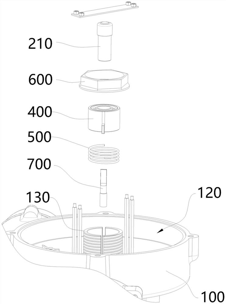
[0025] The present invention will be described in detail in conjunction with accompanying drawing now. This figure is a simplified schematic diagram only illustrating the basic structure of the present invention in a schematic manner, so it only shows the components relevant to the present invention.

[0026] Such as figure 1 and 2 As shown, the present invention provides a valve actuator, including a housing 100, a magnetic member 200 and a Hall element 300, the housing 100 has an output shaft 110 for output torque, and the magnetic member 200 is coaxial with the output shaft 110 set, and the magnetic part 200 is connected to the tail end of the output shaft 110, the Hall element 300 is fixedly arranged on the housing 100, and the Hall element 300 is opposite to the magnetic part 200, when the magnetic part 200 rotates with the output shaft 110 The change of the magnetic field of the magnetic member 400 is sensed by the Hall element 300 , so as to recognize the rotation ang...


PUM


Abstract

The invention discloses a valve actuator, and belongs to the related technical field of valve actuators. The valve actuator mainly comprises a shell, wherein an output shaft used for outputting torque is arranged in the shell, the valve actuator further comprises a magnetic part and a Hall element, the magnetic part and the output shaft are coaxially arranged, the magnetic part is connected with the output shaft, the Hall element is fixed to the shell, the Hall element and the magnetic part are oppositely arranged, and the Hall element is used for sensing change of a magnetic field of the magnetic part when the magnetic part rotates along with the output shaft, so that position feedback of the output shaft is achieved. According to the valve actuator, effects of rapid operation or high-frequency operation of the valve actuator on the feedback precision of the valve actuator can be avoided.

Description

technical field [0001] The invention relates to the related technical field of valve actuators, in particular to a valve actuator. Background technique [0002] The valve actuator needs to feedback and adjust the angular displacement, number of turns or angular velocity of the output shaft through the feedback system to optimize the control accuracy of the valve actuator. For the rotary valve actuator, the existing valve actuator feeds back the output shaft through the potentiometer. The output shaft of the specific valve actuator drives the rotation shaft of the potentiometer to rotate during operation, and the resistance generated by the different rotation positions of the rotation shaft of the potentiometer is utilized. The value of the potentiometer is different, so as to realize the signal feedback, but because the existing valve actuator realizes the signal feedback through the contact structure, the contact friction heat is more obvious, and the resistance of the pote...

Claims


Application Information

Patent Timeline
IPC IPC(8): F16K37/00F16K31/00
CPCF16K37/0041F16K31/00
Inventor 顾荣玉梁军王红明
Owner 江苏海博流体控制有限公司
Learn More