Magnetic engine

An engine and magnet technology, applied in the field of magnetic engines, can solve the problems of emissions, carbon emissions, environmental disadvantages, etc.

Pending Publication Date: 2021-09-10
郁晨
View PDF0 Cites 0 Cited by
  • Summary
  • Abstract
  • Description
  • Claims
  • Application Information

AI Technical Summary

Problems solved by technology

[0002] An engine, also known as an engine, is a machine that can convert other forms of energy into mechanical energy. At present, internal combustion engines are mainly used in civilian use. Internal combustion engines usually convert chemical energy into mechanical energy. It is a reciprocating piston engine. It burns fuel inside to do work, but burning fuel will generate carbon emissions, which is not good for the environment. In order to reduce carbon emissions, electric motors can be used to replace internal combustion engines. However, electric motors need electric energy to run, and electric energy also comes from traditional thermal power, Hydropower and wind power, among them, thermal power accounts for a relatively high proportion. However, thermal power is also obtained by consuming fuel, which still produces a large amount of carbon emissions; and how to provide a green new energy engine has become an urgent need to solve The problem

Method used


Image

  • Magnetic engine
  • Magnetic engine
  • Magnetic engine

Examples


Embodiment 1

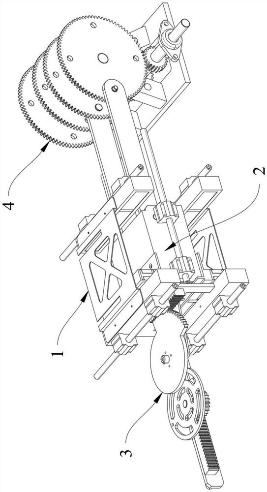
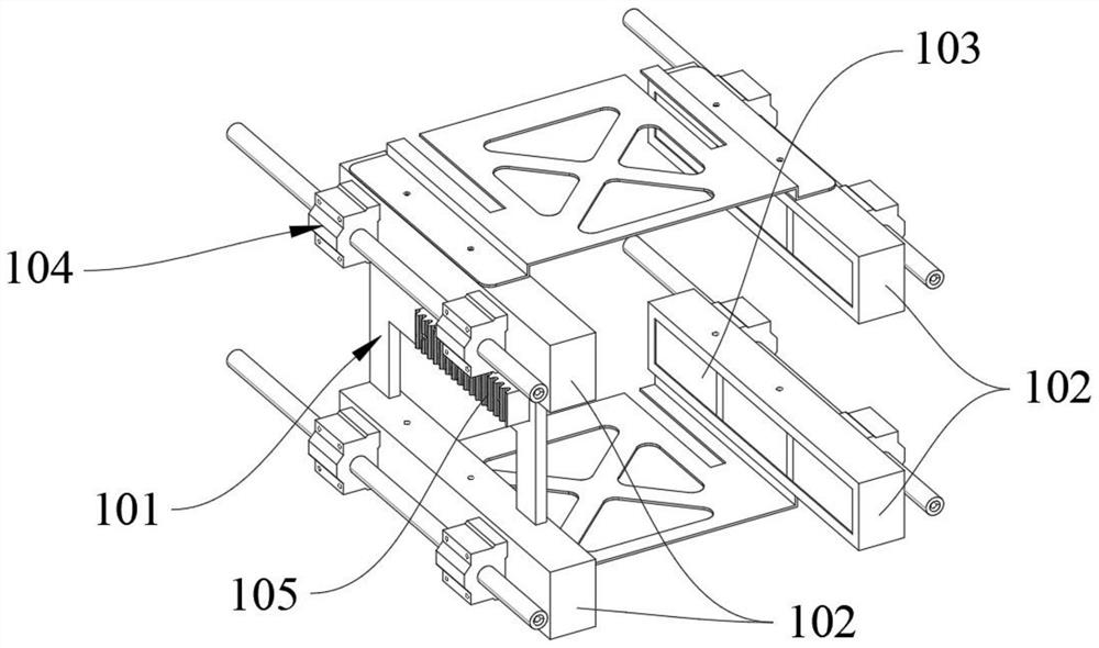
[0039] Please refer to Figure 1 to Figure 11 As shown, this embodiment provides a magnetic engine, including a magnetic power unit; the magnetic power unit includes a magnetic frame 1, a magnetic slider 2 and a magnetic pole switching mechanism 3; the magnetic frame 1 is mounted with a first moving part 104, for providing the magnetic frame 1 with a degree of freedom of reciprocating movement in the front-rear direction, or for providing the magnetic frame 1 with a degree of freedom of reciprocating movement in the circumferential direction of a circle, wherein the axial direction of the circle is the left-right direction; the A second moving part 204 is installed on the magnetic slider 2 to provide the magnetic slider 2 with a degree of freedom of reciprocating movement along the left and right directions; the magnetic frame 1 is respectively provided with a left side and a right side The first magnetic part 102; the first magnetic part 102 includes at least two first magnet...

Embodiment 2

[0049] Please refer to Figure 12As shown, the difference between this embodiment and Embodiment 1 is that the magnetic pole switching mechanism 3 is a second rack and pinion transmission mechanism; the second rack and pinion transmission mechanism includes a The first rack 3b1, the fan-shaped tooth fork 3b2, the rotating wheel 3b4, the gear 3b7 coaxially connected with the rotating wheel 3b4, the second rack 3b8 meshing with the gear 3b7 and installed on the second power transmission part 205; The tooth fork 3b2 is provided with a tooth portion 3b3 that cooperates with the first rack 3b1; the rotating wheel 3b4 is provided with a dial 3b5 near the outer peripheral side, and the sector-shaped tine 3b2 is also provided with a guide that cooperates with the dial 3b5. Slot 3b6; the second power transmission part 205 is used to drive the rotating wheel 3b4 to rotate through the second rack 3b8 to drive the gear 3b7, and then drive the shifting column 3b5 to move, and the cooperati...

Embodiment 3

[0051] Please refer to Figure 13 As shown, the difference between this embodiment and Embodiment 1 is that the magnetic pole switching mechanism 3 is a hydraulic transmission mechanism; the hydraulic transmission mechanism includes a first hydraulic cylinder 3c1, a second hydraulic cylinder 3c2, and a third hydraulic cylinder 3c3; The first hydraulic cylinder 3c1, the second hydraulic cylinder 3c2, and the third hydraulic cylinder 3c3 all include a piston rod, a first oil chamber for controlling the retraction of the piston rod, and a second oil chamber for controlling the extension of the piston rod; The piston rod of a hydraulic cylinder 3c1 is connected to the left end of the first power transmission part 105; the piston rod of the second hydraulic cylinder 3c2 and the piston rod of the third hydraulic cylinder 3c3 are respectively connected to the front end and the rear end of the second power transmission part 205 ; The first oil chamber of the first hydraulic cylinder 3...


PUM


Abstract

The invention relates to a magnetic engine, which comprises a magnetic power unit, wherein the magnetic power unit comprises a magnetic frame, a magnetic sliding block and a magnetic pole switching mechanism, a first moving part is mounted on the magnetic frame, a second moving part is mounted on the magnetic sliding block, first magnetic parts are arranged on the left side and the right side of the magnetic frame respectively, the first magnetic part comprises at least two first magnets, the first magnets are distributed in the front-back direction or the circumferential direction of a circle, a second magnetic part is mounted on the magnetic sliding block, the second magnetic part comprises at least one second magnet, the second magnet is located between the two first magnetic parts, N poles and S poles are arranged at the two ends of the first magnet and the second magnet in the left-right direction, the magnetic poles of the same-direction ends of the two adjacent first magnets of the first magnetic parts on the same side are opposite, and the magnetic poles of the same-direction ends of the two first magnets corresponding to the positions of the first magnetic parts on the two sides are opposite. According to the invention, the magnetic engine utilizes magnetic energy to act, is reasonable in design, compact in structure and high in expansibility, and meets different power requirements.

Description

technical field [0001] The invention relates to the field of engine equipment, in particular to a magnetic engine. Background technique [0002] An engine, also known as an engine, is a machine that can convert other forms of energy into mechanical energy. At present, internal combustion engines are mainly used in civilian use. Internal combustion engines usually convert chemical energy into mechanical energy. It is a reciprocating piston engine. It burns fuel inside to do work, but burning fuel will generate carbon emissions, which is not good for the environment. In order to reduce carbon emissions, electric motors can be used to replace internal combustion engines. However, electric motors need electric energy to run, and electric energy also comes from traditional thermal power, Hydropower and wind power, among them, thermal power accounts for a relatively high proportion. However, thermal power is also obtained by consuming fuel, which still produces a large amount of c...

Claims


Application Information

Patent Timeline
Patent Type & Authority Applications(China)
IPC IPC(8): H02K53/00
CPCH02K53/00
Inventor 郁晨
Owner 郁晨
Why Eureka
Try Eureka