


Quick Research
Generate reliable direction feasibility study reports for your R&D in just a few steps.

Technical Q&A
Discover and master advanced knowledge NOW. Basics, ideas, possibilities, all at once.

Find Solutions
As an expert in R&D theories, this can generate solutions to your technical problems instantly.

Evaluate Feasibility
Analyze your overall solution with one click, know your potential R&D risks in advance.

Monitor Landscape
Get weekly tech updates, stay abreast of the latest tech innovations and key insights.
A Judgment Method for Machinability of Compensation Layer of Aircraft Parts
A technology of aircraft parts and compensation layers, applied in the direction of sustainable transportation, instruments, geometric CAD, etc., can solve the problems of insufficient machinability judgment methods, low efficiency, debonding, etc., to ensure work efficiency, low cost, and easy implementation Effect
- Summary
- Abstract
- Description
- Claims
- Application Information
AI Technical Summary
Problems solved by technology
Method used
Image

Examples
Embodiment 1
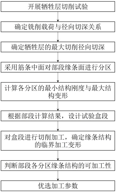
[0069] This embodiment discloses a method for judging the machinability of an aircraft component compensation layer, as a basic implementation of the present invention, such as figure 1 shown, including the following steps:
[0070] S1, design the cutting test, obtain the law between the cutting load and the cutting parameters through the cutting test, and determine the limit cutting parameters;
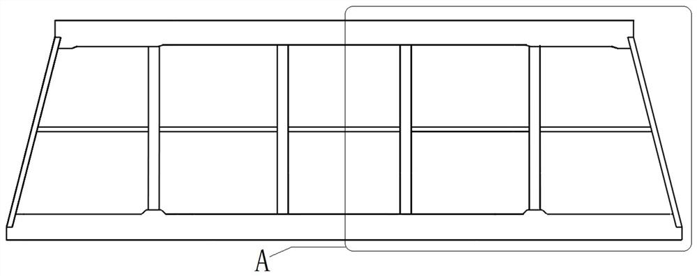
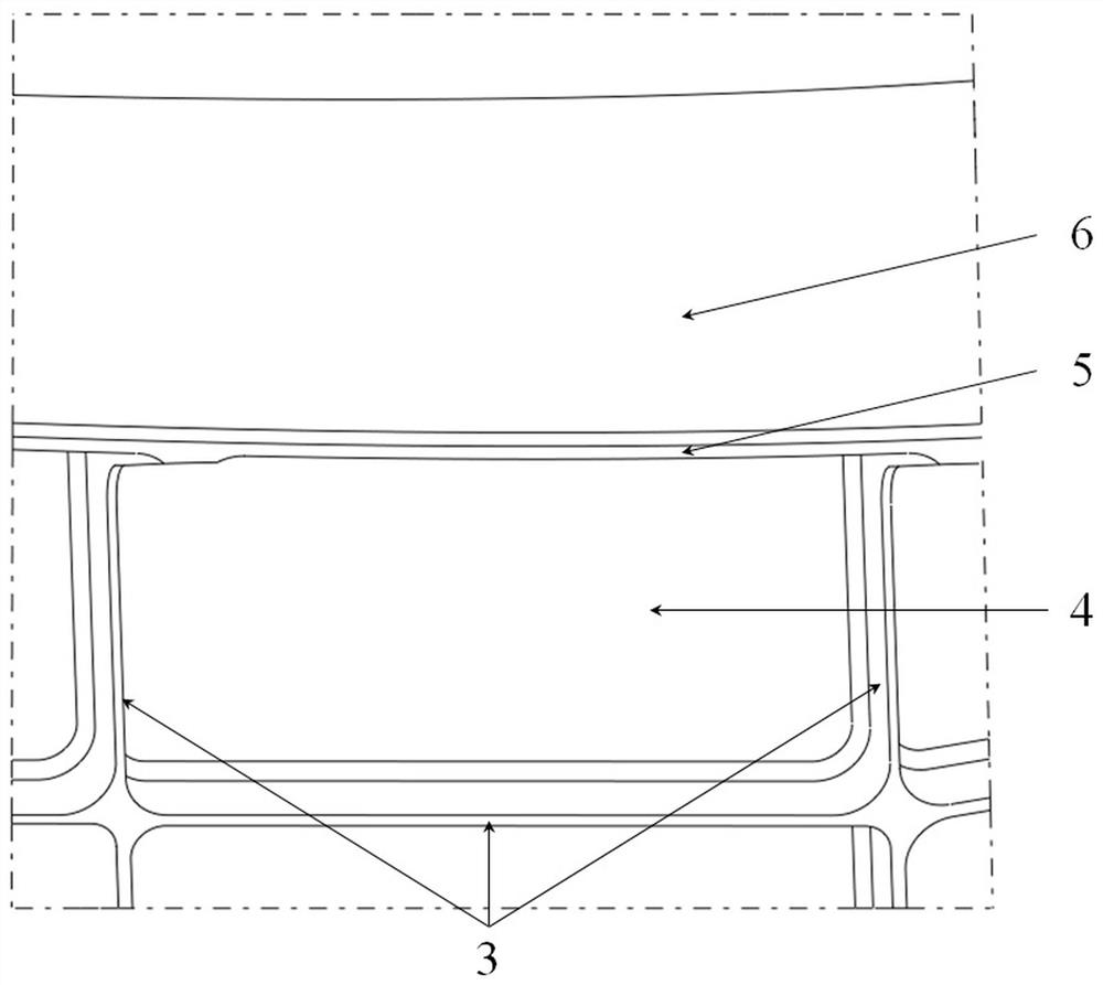
[0071] S2, combined with the structural characteristics of the section (the section structure is left-right symmetrical, bounded by the mid-plane of the web of the rib, frame and beam, and the edge of the edge), the processing surface of the compensation layer liner is divided to form Section processing area, such as Figure 6 and Figure 7 As shown, it is divided into 83 section processing areas, Figure 7 (1-1)~(1-83) in each represent a section processing area, and each section processing area has a relative stiffness minimum point ( Figure 8 As shown, the edge of the compe...
Embodiment 2
[0086] This example discloses a method for judging the machinability of an aircraft component compensation layer. As a preferred embodiment of the present invention, that is, in Example 1, the cutting test in step S1 is to select EW100 fiberglass composite material as the compensation layer lining Pad, carry out mechanical performance test, and calibrate the cutting mechanical performance of compensation layer pad, including the following steps:
[0087] S1-1, bonding a 2mm thick compensation layer liner on the aluminum alloy plate;
[0088] S1-2, the bottom of the aluminum alloy plate is connected to the dynamometer, and the dynamometer is directly below the pad of the compensation layer, such as Figure 5 shown;
[0089] S1-3, based on the numerical control system of the machine tool, set the processing parameters for the compensation layer liner. Among the processing parameters, the radial depth of cut ; Preferably, the cutting tool used by the machine tool for processin...
Embodiment 3
[0096] This example discloses a method for judging the machinability of an aircraft component compensation layer. As a preferred embodiment of the present invention, that is, in Example 2, the limit cutting parameter in step S1 is the maximum machinable value of the compensation layer liner. radial depth of cut , and the maximum radial depth of cut is based on the bond-peel strength of the compensation liner To determine the bond-peel strength of the compensation layer liner Including the tear-off strength between the FRP composite material and the glue and the tear-off strength between the aluminum alloy plate and the glue is , then the maximum radial depth of cut The determination includes the following steps:
[0097] S1-6, based on , combined with of axis, axis and range of axis orientations, obtain the formula and , then during the cutting process, the tangential cutting load borne by the compensation layer liner ;
[0098] S1-7, order and ...
PUM
 Abstract
Description
Claims
Application Information
 - R&D Engineer
- R&D Manager
- IP Professional
- Industry Leading Data Capabilities
- Powerful AI technology
- Patent DNA Extraction
Browse by: Latest US Patents, China's latest patents, Technical Efficacy Thesaurus, Application Domain, Technology Topic, Popular Technical Reports.
© 2024 PatSnap. All rights reserved.Legal|Privacy policy|Modern Slavery Act Transparency Statement|Sitemap|About US| Contact US: help@patsnap.com