
Calibration process and device for double-shaft high-resolution magnetoelectric encoder

A magnetoelectric encoder and high-resolution technology, applied in the field of magnetoelectric encoders, can solve the problems of low flexibility, low degree of automation, difficulty in mass production and application, etc.

Active Publication Date: 2021-09-10
HARBIN UNIV OF SCI & TECH
View PDF6 Cites 3 Cited by
  • Summary
  • Abstract
  • Description
  • Claims
  • Application Information

AI Technical Summary

Problems solved by technology

[0003] However, since the angular displacement calculation accuracy of the magnetoelectric encoder is affected by the process of integrating the permanent magnets into the inner and outer magnetic rings by bonding, there are large installation errors and position errors, so its resolution is relatively low. The photoelectric encoders widely used in the market are relatively low. Therefore, it is usually necessary to use a photoelectric encoder with high measurement accuracy to calibrate the magnetoelectric encoder. However, the traditional magnetoelectric encoder calibration device uses a magnetic The electrical encoder and the photoelectric encoder are coaxially connected together, and the difference in the effect of improving the resolution of the encoder may be relatively large, and its degree of automation is low, and its flexibility is low, which is not easy for commercial mass production and application

Method used


Image

  • Calibration process and device for double-shaft high-resolution magnetoelectric encoder
  • Calibration process and device for double-shaft high-resolution magnetoelectric encoder
  • Calibration process and device for double-shaft high-resolution magnetoelectric encoder

Examples


Embodiment Construction

[0039] The calibration process and device of a dual-axis high-resolution magnetoelectric encoder proposed by the present invention will be further described in detail below in conjunction with the accompanying drawings and specific embodiments. Advantages and features of the present invention will be apparent from the following description and claims.

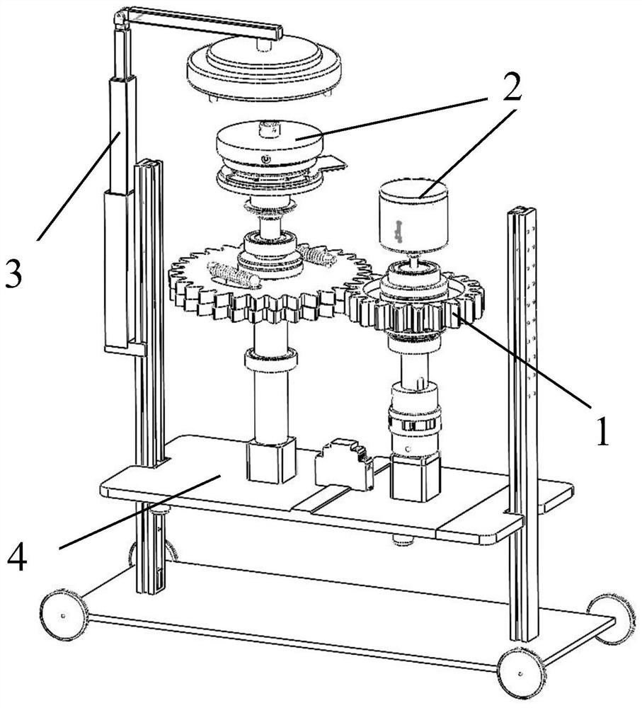
[0040] see figure 1 as shown, figure 1 It is a perspective view of a dual-axis high-resolution magnetoelectric encoder calibration device system, including a dual-axis transmission mechanism 1, a measuring device 2, a lifting platform 3, a mechanical arm adjustment mechanism 4, and an electrical control system 6.

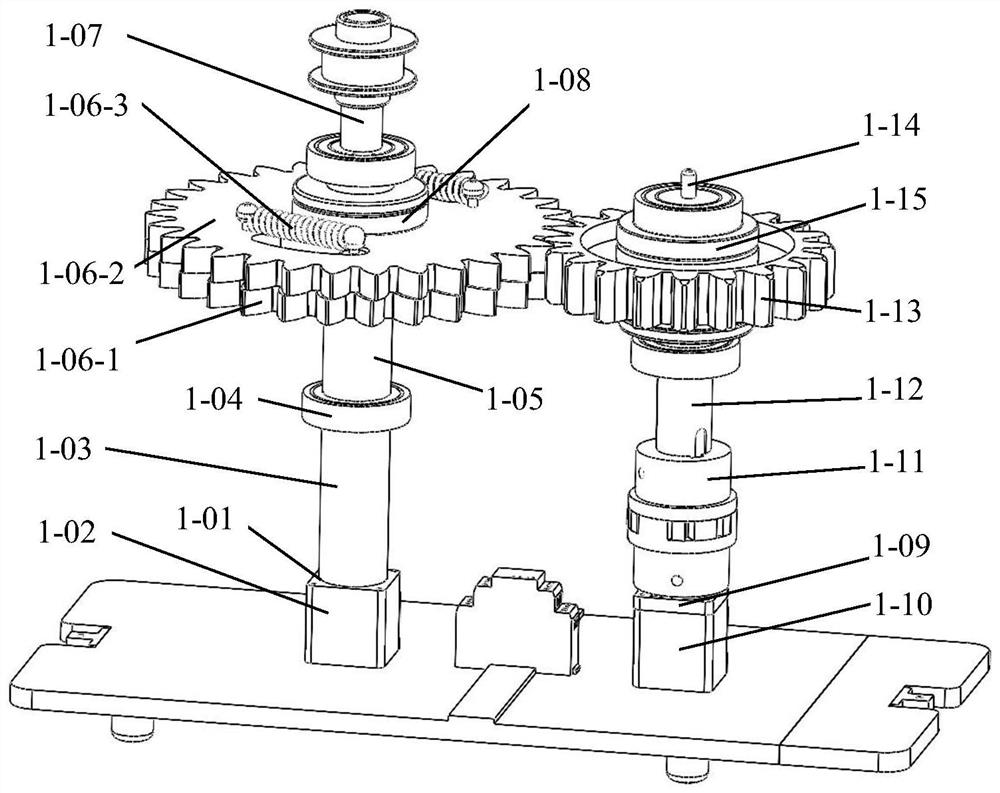
[0041] see figure 2 as shown, figure 2 for figure 1 Schematic diagram of the double-axis transmission mechanism 1, the double-axis transmission mechanism 1 includes a magnetoelectric shaft servo motor 1-01, a magnetoelectric shaft servo motor mounting bracket 1-02, a support shaft 1-03, a bearing 1-04, and a lo...


PUM


Abstract

The invention discloses a calibration process and device for a double-shaft high-resolution magnetoelectric encoder. The device comprises a double-shaft transmission mechanism, a measuring device, a lifting platform, a mechanical arm adjusting mechanism and an electrical control system. A servo motor of the double-shaft transmission mechanism is fixedly mounted on a lifting plate, and provides a power source and transmits power for the whole measuring device system; the measuring device is used for collecting angular displacement signals of the output end of the motor shaft and transmitting the angular displacement signals to the control system to achieve sampling and transmission of measured signals. The lifting platform and the mechanical arm adjusting mechanism consider the flexibility and practicability of the whole device to realize large-scale batch production and application of the whole device system; the electrical control system is used for collecting, analyzing and calculating data of a signal output end, and rapidly transmitting the sampled data to an upper computer for data processing, analysis and calculation through a plurality of usb channels of the multichannel isolation data collector, so as to finally obtain angular displacement information of the high-resolution encoder. The calibration device for the double-shaft high-resolution magnetoelectric encoder is high in encoder automation degree, good in universality and flexible to operate, gear transmission return stroke errors of the device can be eliminated, the system resolution is improved, and commercial mass production and application are easy.

Description

technical field [0001] The present invention generally relates to a magnetoelectric encoder, and specifically relates to a calibration process and device for a biaxial high-resolution magnetoelectric encoder. Background technique [0002] Magnetoelectric encoder is a kind of measuring device. Its principle is to measure the angle or displacement of magnetic material by using sensors such as reluctance or Hall elements. The magnetic material is bonded to the rotor and rotates, and the air gap between the rotor and the stator changes The magnetic field signal, the Hall element collects the magnetic field signal, and outputs the digital signal through the analog-to-digital conversion module. The signal processing board performs calculation to realize angle measurement. Magnetic encoders have the characteristics of anti-vibration, anti-corrosion, anti-pollution, anti-interference and wide temperature, so they can be widely used in machinery manufacturing, shipbuilding, textile,...

Claims


Application Information

Patent Timeline
IPC IPC(8): G01D18/00
CPCG01D18/00
Inventor 王磊杨英杰刘仁萨
Owner HARBIN UNIV OF SCI & TECH
Learn More