
A motor end cover manufacturing and processing fixing device

A motor end and fixing device technology, which is applied to manufacturing tools, positioning devices, workpiece clamping devices, etc., can solve the problems of high manufacturing and processing cost of motor end caps, shortened service life of motor end caps, and easy corrosion of motor end caps. , to avoid frequent replacement of equipment, support a wide range of limits, and reduce the number of equipment used

Active Publication Date: 2021-10-26
徐州汇易容金属科技有限公司
View PDF0 Cites 1 Cited by
  • Summary
  • Abstract
  • Description
  • Claims
  • Application Information

AI Technical Summary

Problems solved by technology

[0003] At present, the following problems exist in the process of manufacturing, processing and fixing the motor end cover: a. During the clamping and limiting process of the traditional motor end cover, due to the different models and specifications of the motor, the traditional motor end cover clamping and limiting equipment can only be used for a single specification The clamping limit of the motor end cover, when it is necessary to clamp the motor end cover of different specifications, it is necessary to frequently replace the clamping limit device, which makes the process cumbersome and causes high manufacturing and processing costs of the motor end cover, b traditional motor end cover During the clamping and limiting process, since the motor end cover needs to be rotated during the finishing process such as grinding and painting, the motor end cover may slide relative to each other during the rotation process, which will affect the subsequent grinding, painting, etc. of the motor end cover. As a result of the finishing process, the motor end cover is prone to corrosion, resulting in a shortened service life of the motor end cover

Method used


Image

  • A motor end cover manufacturing and processing fixing device
  • A motor end cover manufacturing and processing fixing device
  • A motor end cover manufacturing and processing fixing device

Examples


Embodiment Construction

[0027] The embodiments of the present invention will be described in detail below with reference to the accompanying drawings, but the present invention can be implemented in many different ways defined and covered by the claims.

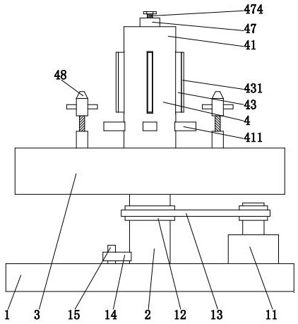
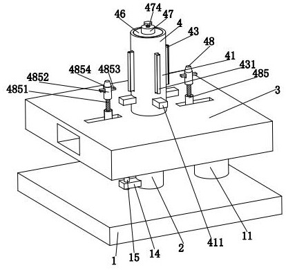
[0028] Such as Figure 1 to Figure 9 As shown, a motor end cover manufacturing and processing fixing device includes a bottom frame 1, a connecting shaft 2, a fixed frame 3 and a clamping and limiting mechanism 4. The upper end surface of the bottom frame 1 is provided with a connecting shaft 2, A fixed frame 3 is installed on the upper end surface of the connecting shaft 2, and a clamping and limiting mechanism 4 is installed on the upper end surface of the fixed frame 3.

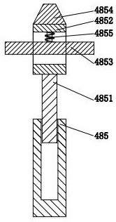
[0029] refer to figure 2 and Figure 4, the clamping and limiting mechanism 4 includes a clamping cylinder 41, a rotating roller 42, a clamping plate 43, a support frame 44, a return spring rod 45, a cover plate 46, a rotating shaft 47 and a limiting branch chain 48, wherein ...


PUM


Abstract

The invention relates to the technical field of motor end cover processing, in particular to a motor end cover manufacturing and fixing device, including a bottom frame, a connecting shaft, a fixed frame and a clamping and limiting mechanism; the present invention can solve the following problems: the traditional motor During the clamping and limiting process of the end cover, due to the different models and specifications of the motor, the traditional motor end cover clamping and limiting device can only clamp and limit the motor end cover of a single specification; the motor end cover may occur during the rotation process. Relative sliding; the present invention cooperates with the arc-shaped projection on the rotating roller and the support frame to drive the clamping plate to support the motor end covers of different specifications, so that the clamping limit mechanism has a wider range of support and limit, In the limiting branch chain of the present invention, the limiting frame can limit the position of the motor end cover through the mutual cooperation of the traction rope and the moving block, so as to ensure that the motor end cover will not rotate relative to each other during the finishing process.

Description

technical field [0001] The invention relates to the technical field of motor end cover processing, in particular to a manufacturing and processing fixing device for a motor end cover. Background technique [0002] A motor is a device that converts electrical energy into mechanical energy. It is composed of a stator, a rotor and other accessories. After removing the stator and rotor, other accessories include end covers, bearings, bearing end covers, and fans. The motor end cover is in the motor. The composition plays a supporting role for the motor. The motor end cover is a workpiece obtained by pouring, cooling, demoulding and finishing of molten iron. Due to factors such as moisture, acid and alkali may exist in the use of the motor, the motor end cover Finishing treatment such as grinding and painting is required after forming. The motor end cover needs to be clamped and fixed during the finishing process to avoid shaking of the motor end cover during the finishing proces...

Claims


Application Information

Patent Timeline
Patent Type & Authority Patents(China)
IPC IPC(8): B23Q3/06B25B11/00
CPCB23Q3/06B25B11/00
Inventor 杜卫东
Owner 徐州汇易容金属科技有限公司
Learn More