Parking brake assembly with abs control for each individual wheel

A technology of parking brakes and facilities, applied in the direction of ABS control system, brake, brake type, etc., can solve problems such as the inability to use the brake system

Active Publication Date: 2021-09-07
ZF CV SYST HANNOVER GMBH
View PDF10 Cites 0 Cited by
  • Summary
  • Abstract
  • Description
  • Claims
  • Application Information

AI Technical Summary

Problems solved by technology

The disadvantage here is that this only works adequately for electronically controllable braking systems, but not for purely pneumatic braking systems

Method used


Image

  • Parking brake assembly with abs control for each individual wheel
  • Parking brake assembly with abs control for each individual wheel
  • Parking brake assembly with abs control for each individual wheel

Examples


Embodiment Construction

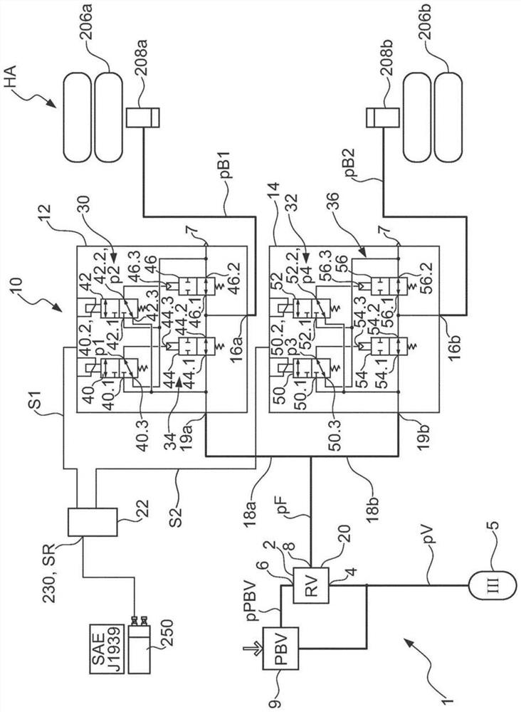
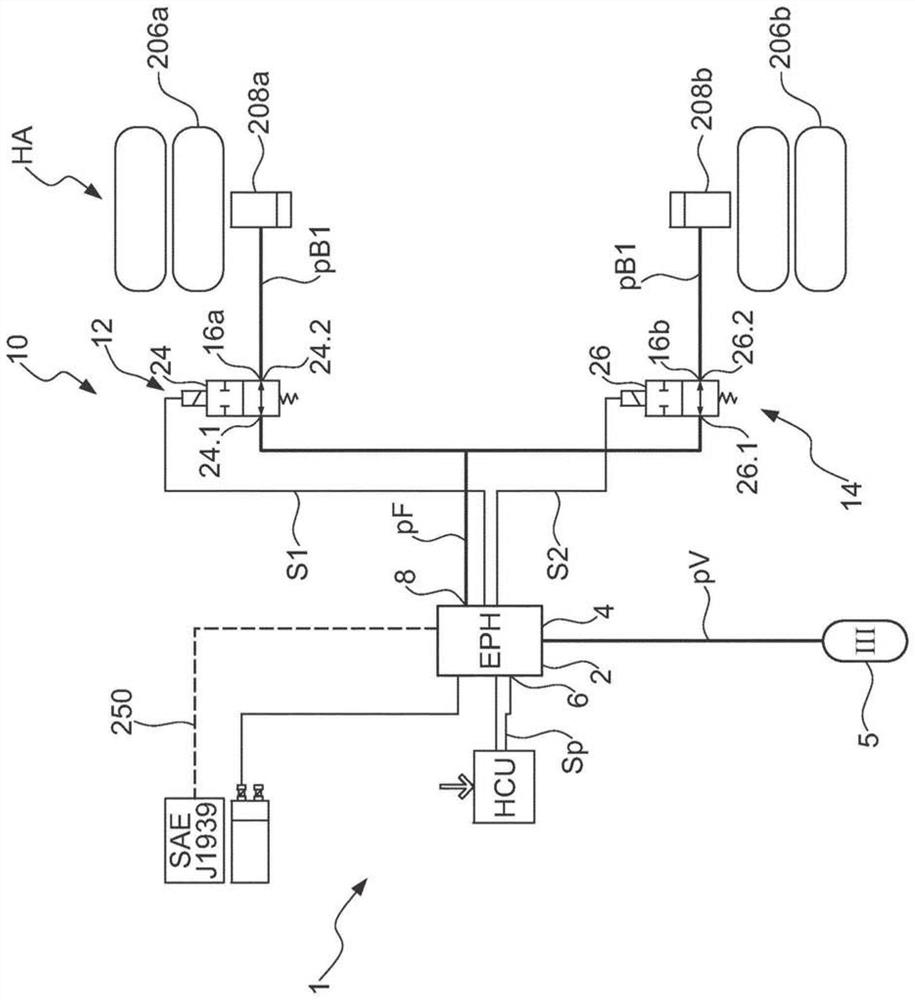
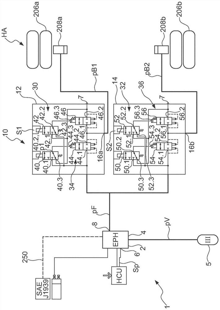
[0045] Parking brake facility 1 ( figure 1 ) is set in electronically controlled pneumatic braking system 204 (see Figure 7-9 )middle. The parking brake system 1 has a parking brake unit 2 , which itself is designed to set a parking brake pressure pF. This parking brake pressure pF is usually supplied to the first and second spring-charged brake cylinders 208 a , 208 b in order to charge them and thus open them during driving operation. When the vehicle 200 is about to stop, the parking brake pressure is reduced by the parking brake unit, preferably down to ambient pressure, so that the spring-charged brake cylinders 208a, 208b are compressed.

[0046] For this purpose, the parking brake unit 2 is supplied with a reserve pressure pV from a compressed air reserve 5 via the reserve connection 4 . Furthermore, the parking brake unit 2 has a brake request connection 6 for receiving a parking brake request pPBV and a parking brake pressure connection 8 for providing a parking b...


PUM


Abstract

The invention relates to a parking brake assembly (1) for an electronically controllable pneumatic brake system (204) for a utility vehicle (202), comprising a parking brake unit (2) which has an accumulator connection (4) for receiving an accumulator pressure (pV), a brake request connection (6) for receiving a parking brake request (pPBV, SP), and a parking brake connection (8) for providing a parking brake pressure (pF). An ABS valve assembly (10) is provided which has a first ABS valve unit (12) for a first channel (16a) and a second ABS valve unit (14) for a second channel (16b). The first ABS valve unit (12) receives the parking brake pressure (pF) and provides a first brake pressure (pB1) on the first channel (16a), and the first ABS valve unit (12) is designed to ventilate the first channel (16a) at least in stages. The second ABS valve unit (14) receives the parking brake pressure (pF) and provides a second brake pressure (pB2) on the second channel (16b), and the second ABS valve unit (12) is designed to ventilate the second channel (16b) at least in stages.

Description

technical field [0001] The invention relates to a parking brake arrangement for an electronically controllable pneumatic brake system for a vehicle, in particular a commercial vehicle, having a parking brake unit with a reserve connection for receiving a reserve pressure , a brake request interface for receiving a parking brake request and a parking brake pressure interface for providing parking brake pressure. [0002] The invention also relates to an electronically controllable pneumatic braking system having such a parking brake arrangement and to a method for controlling the electronically controllable pneumatic braking system. Background technique [0003] Such parking brake arrangements are used in vehicles, in particular commercial vehicles, to stop the vehicle in a parked state. As a rule, such a parking brake arrangement acts on the spring accumulator part of a so-called spring accumulator brake or a combined brake cylinder, which is usually arranged on the rear ax...

Claims


Application Information

Patent Timeline
Patent Type & Authority Applications(China)
IPC IPC(8): B60T7/08B60T8/36B60T13/68B60T8/88
CPCB60T8/362B60T13/683B60T7/08B60T8/88B60T13/662B60T2201/10F16D66/00B60T8/176B60T15/027B60T17/083B60T2201/12B60T2270/10
Inventor 朱利安·万蒂勒乌韦·本施
Owner ZF CV SYST HANNOVER GMBH
Why Eureka
Try Eureka