
Installation method for multi-support long shaft system of 1000MW-level steam turbine generator unit

A technology of a steam turbine generator set and an installation method, which is applied in the directions of engine components, machines/engines, mechanical equipment, etc., can solve the problems of shortening the installation time of the shafting, difficulty in the installation of large-capacity and multi-support long shaftings, etc.

Pending Publication Date: 2021-09-07
中电建湖北电力建设有限公司
View PDF4 Cites 0 Cited by
  • Summary
  • Abstract
  • Description
  • Claims
  • Application Information

AI Technical Summary

Problems solved by technology

[0005] The present invention provides an installation method for a multi-support long shaft system of a 1000MW steam turbine generator set aiming at the difficult installation problem of the existing large-capacity multi-support long shaft system. Control the vertical lift and horizontal degree of each platen and bearing seat, so that the grinding contact of the bearing pad is uniform and good, and the center between the rotors of the shafting system can be measured and detected to ensure the centering effect of the shafting system and ensure the installation of the entire shafting system Accuracy, shorten the installation time of the shaft system, and ensure the stable operation of the generator set

Method used


Image

  • Installation method for multi-support long shaft system of 1000MW-level steam turbine generator unit
  • Installation method for multi-support long shaft system of 1000MW-level steam turbine generator unit
  • Installation method for multi-support long shaft system of 1000MW-level steam turbine generator unit

Examples


Embodiment Construction

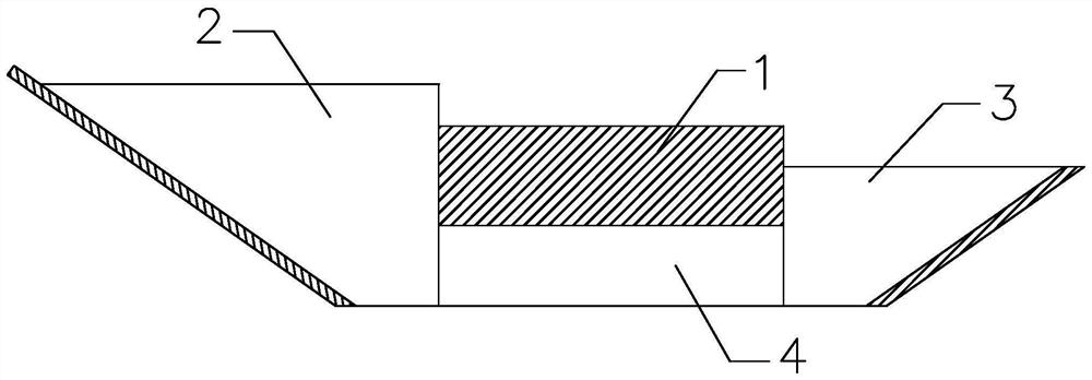
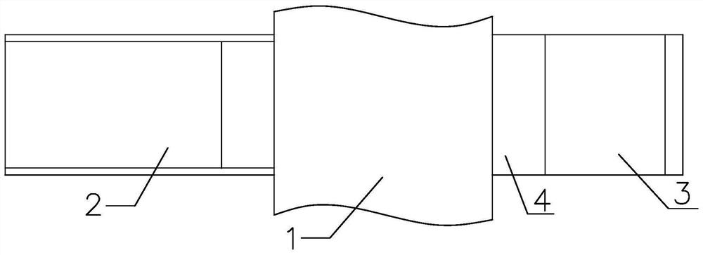
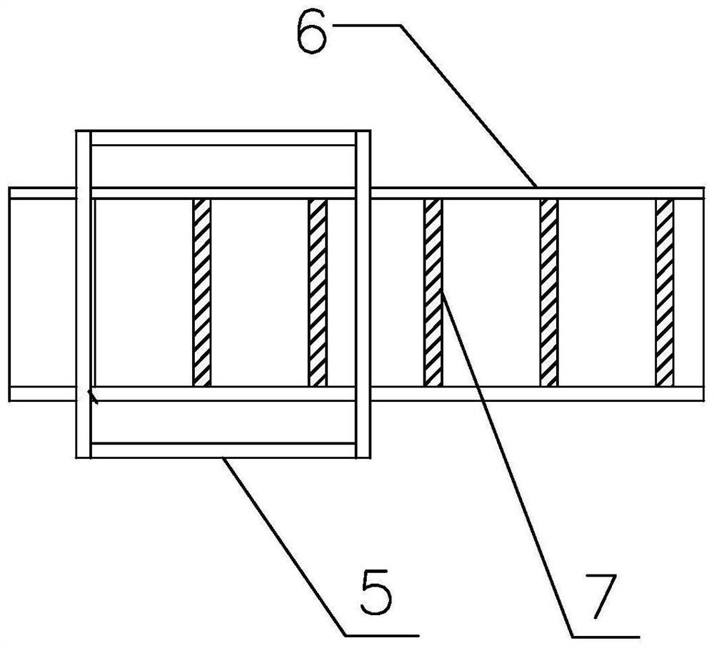
[0053] The present invention will be further described below in conjunction with drawings and embodiments. attached Figure 1 to Figure 14 All are drawings of embodiments, drawn in a simplified manner, and are only used for the purpose of clearly and concisely illustrating the embodiments of the present invention. The following technical solutions shown in the drawings are specific solutions of the embodiments of the present invention, and are not intended to limit the scope of the claimed invention. Based on the embodiments of the present invention, all other embodiments obtained by persons of ordinary skill in the art without creative efforts fall within the protection scope of the present invention.

[0054] In the description of the present invention, it should be understood that the orientations or positional relationships indicated by the terms "upper", "lower", "inner", "outer", "left", "right" etc. are based on those shown in the accompanying drawings. Orientation or...


PUM


Abstract

The invention provides an installation method for a multi-support long shaft system of a 1000MW-level steam turbine generator unit. The installation method comprises the following steps: (1) adjusting a bedplate and adjusting a bearing seat in place; (2) grouting and pouring a cement cushion block by adopting a special mold box and a flow guide groove with a defoaming strip; (3) placing a low-pressure cylinder and the bearing seat in place; (4) carrying out limiting grinding on a bearing bush of the low-pressure cylinder by using a bearing bush grinding limiting tool; (5) hoisting a generator stator and a high-pressure cylinder; (6) penetrating a generator rotor into a generator stator chamber by adopting a traveling-matched slippage method; (7) adjusting an air gap between the generator rotor and the generator stator, and a magnetic center of the generator; (8) centering the shaft system; (9) measuring and adjusting the center of a partition plate, a steam seal radial clearance and a through-flow axial clearance; and (10) buckling a cylinder cover, carrying out secondary pouring on a foundation, rechecking the center of the shaft system, and carrying out coupling connection. According to the invention, the installation time for the shaft system is greatly shortened, the installation quality is reliable, and stable operation of a generator unit can be ensured.

Description

technical field [0001] The invention relates to the installation of multi-supported long shafts of a turbo-generator set in a thermal power plant, in particular to a method for installing a multi-supported long shaft of a 1000MW class turbo-generator. Background technique [0002] As the country's energy-saving and environmental protection requirements are getting higher and higher, thermal power generation units with high parameters, large capacity and high efficiency are developing rapidly. Among them, ultra-supercritical 1 million units have gradually become the main model of coal-fired power unit production due to their environmental protection and high efficiency. [0003] The 1000MW turbogenerator set adopts five rotors and eleven bearing bushes to support the excitation brush holder bearing as a stable bearing. The total length of the turbogenerator set is 54.6m. The entire turbogenerator set shaft system includes the generator rotor, B low-pressure rotor, and A low-v...

Claims


Application Information

Patent Timeline
IPC IPC(8): F01D25/28
CPCF01D25/28F01D25/285
Inventor 段勇刚陈庚文朱永玖龚新义郑云鹏
Owner 中电建湖北电力建设有限公司
Learn More