
Ultrasonic electric spindle and electromagnetic isolation structure thereof

A technology of electromagnetic isolation and electric spindle, which is applied in the direction of large fixed members, metal processing machinery parts, maintenance and safety accessories, etc., and can solve problems such as encoder interference and encoder signal instability

Pending Publication Date: 2021-09-07
CONPROFE MACHINE TOOLS CO LTD
View PDF0 Cites 0 Cited by
  • Summary
  • Abstract
  • Description
  • Claims
  • Application Information

AI Technical Summary

Problems solved by technology

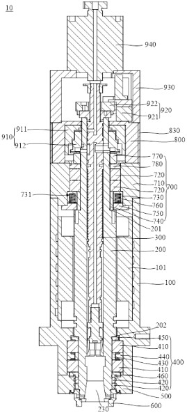
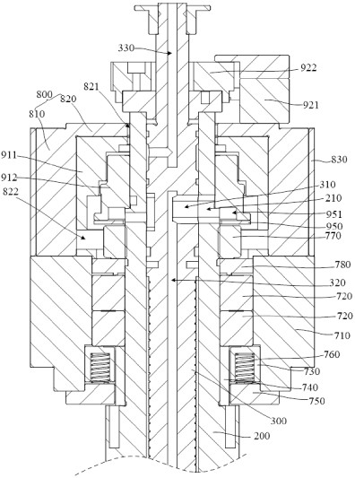
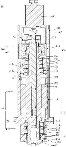
[0003] The traditional ultrasonic electric spindle includes components such as wireless transmitting components, wireless receiving components and encoders. Since the wireless transmitting components and wireless receiving components usually include magnetic cores and coils, they will generate electromagnetic waves during work, and these electromagnetics will affect the encoder. Interference is generated, causing the encoder signal to be unstable

Method used


Image

  • Ultrasonic electric spindle and electromagnetic isolation structure thereof
  • Ultrasonic electric spindle and electromagnetic isolation structure thereof
  • Ultrasonic electric spindle and electromagnetic isolation structure thereof

Examples


Embodiment Construction

[0026] In order to make the above objects, features and advantages of the present invention more comprehensible, specific implementations of the present invention will be described in detail below in conjunction with the accompanying drawings. In the following description, numerous specific details are set forth in order to provide a thorough understanding of the present invention. However, the present invention can be implemented in many other ways different from those described here, and those skilled in the art can make similar improvements without departing from the connotation of the present invention, so the present invention is not limited by the specific implementations disclosed below.

[0027] It should be noted that when an element is referred to as being “fixed” to another element, it can be directly on the other element or there can also be an intervening element. When an element is referred to as being "connected to" another element, it can be directly connected ...


PUM


Abstract

The invention relates to an ultrasonic electric spindle and an electromagnetic isolation structure thereof. The electromagnetic isolation structure comprises a rear end shell, wherein the rear end shell comprises a shell part and a partition plate part. During assembling, a wireless transmitting assembly and a wireless receiving assembly are arranged in an accommodating space jointly defined by the partition plate part and the shell part, and an induction head of an encoder is installed on the rear portion of the partition plate part, so that the induction head of the encoder, the wireless transmitting assembly and the wireless receiving assembly are located on the two different sides of the partition plate part respectively and are isolated by the partition plate part. Therefore during working, even if the wireless transmitting assembly and the wireless receiving assembly generate electromagnetism, the induction head of the encoder on the other side of the partition plate part is not interfered, so that the phenomenon that a signal of the encoder is unstable is effectively avoided.

Description

technical field [0001] The invention relates to the technical field of spindles, in particular to an ultrasonic electric spindle and its electromagnetic isolation structure. Background technique [0002] The spindle is one of the important parts of the machine tool, and its precision directly affects the machining precision. The ultrasonic electric spindle uses the high-frequency vibration of the tool in the axial direction to make the tool rotate at high speed to cut the workpiece, which can reduce the processing resistance, improve the processing efficiency, and obviously improve the roughness of the processed surface. It has the advantages of greatly extending tool life and small residual processing stress. It is suitable for the processing of parts such as strengthened glass and semiconductors, as well as the processing of hard and brittle materials such as quartz and alumina. [0003] The traditional ultrasonic electric spindle includes components such as wireless tran...

Claims


Application Information

Patent Timeline
Patent Type & Authority Applications(China)
IPC IPC(8): B23B19/02B23Q11/00
CPCB23Q1/70B23Q11/00
Inventor 颜炳姜蔡丹邝金田
Owner CONPROFE MACHINE TOOLS CO LTD
Learn More