
Production equipment and method for internal and external high-strength, high-conductivity, wear-resistant copper-steel composite contact wire

A technology for composite contact and production equipment, applied in the field of wire rods, can solve the problems of limited improvement, shorten the service life of the contact wire, and large wear, and achieve the effects of increasing service life, saving electrical conductivity, and strengthening firmness

Active Publication Date: 2022-04-29
CHINA RAILWAY CONSTR ELECTRIFICATION BUREAU GRP KANG YUAN NEW MATERIALS CO LTD
View PDF6 Cites 0 Cited by
  • Summary
  • Abstract
  • Description
  • Claims
  • Application Information

AI Technical Summary

Problems solved by technology

The Cu-Cr-Zr contact wire is still in the laboratory stage or the small batch test stage. Although there is a certain degree of improvement on the original basis, the improvement is limited. Chinese patent CN110660499A provides a large-length melt-infiltrated copper-steel Composite wire greatly enhances the tensile strength of the wire and maintains high electrical conductivity, but the composite part in the middle of this type of alloy material has the highest strength, and the lower part of the contact wire wears a lot after long-term contact with the pantograph, shortening the contact wire Therefore, there is an urgent need for an enhanced wear-resistant large-length, high-strength, and high-conductivity copper-steel composite contact wire to strengthen the wear resistance of the lower part of the contact wire and meet the development requirements of future high-speed railway wire rods.

Method used


Image

  • Production equipment and method for internal and external high-strength, high-conductivity, wear-resistant copper-steel composite contact wire
  • Production equipment and method for internal and external high-strength, high-conductivity, wear-resistant copper-steel composite contact wire
  • Production equipment and method for internal and external high-strength, high-conductivity, wear-resistant copper-steel composite contact wire

Examples


Embodiment 1

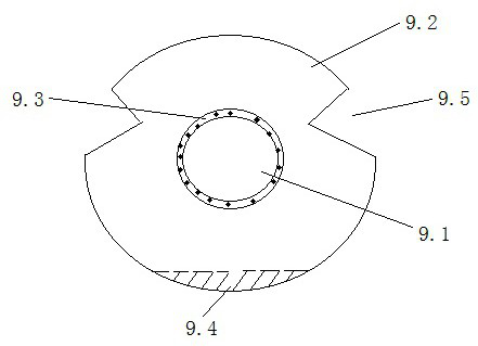
[0031] see Figure 1-2 , figure 1 A schematic diagram of the production equipment for an internal and external high-strength, high-conductivity and wear-resistant copper-steel composite contact wire is drawn. As shown in the figure, the production equipment of internal and external high-strength, high-conductivity and wear-resistant copper-steel composite contact wires involved in the present invention includes a first mold 5, a circulating cooling system 6 and a finishing mold 7; the first mold 5 includes an injection section and In the cooling section, the injection section is provided with five injection ports, respectively injecting steel core 1, copper water 2, copper-magnesium alloy furnace water 3 and copper-steel mixed furnace water 4, and the cooling section is provided with a circulating cooling system 6.

[0032] The first mold 5 is provided with a cylindrical steel core cavity for placing the steel core 1; the outer ring of the steel core cavity is provided with a...


PUM


Abstract

The present invention relates to a production equipment and method for an internal and external high-strength, high-conductivity and wear-resistant copper-steel composite contact wire, which includes a first mold, a circulating cooling system and a finishing mold; the first mold includes an injection section and a cooling section, The injection section is equipped with five injection ports, respectively injecting steel core, copper water, copper-magnesium alloy furnace water and copper-steel mixed furnace water. The cooling section is equipped with a circulating cooling system; The mixed liquid state of furnace water and copper-steel mixed furnace water is cooled to form a solid state; the finishing mold is connected with the cooling section of the first mold for drawing to form a contact line. The bottom of the inventive contact wire is continuously cast with 0.4% copper-magnesium alloy to form a layer of copper-magnesium alloy wear-resistant layer, which increases the wear resistance with the pantograph and reduces the wear of the contact part of the contact wire, thereby increasing the use of the contact wire life.

Description

technical field [0001] The invention relates to the field of wire rods, in particular to a production equipment and method for an internal and external high-strength, high-conductivity and wear-resistant copper-steel composite contact wire. Background technique [0002] With the development of electronic information technology, the requirements for the comprehensive performance of copper alloy conductive materials are getting higher and higher. It is required to maintain high electrical conductivity and thermal conductivity while maintaining high strength (hardness), toughness, and wear resistance. Sex, cold resistance, non-ferromagnetic and other characteristics. These excellent properties make copper alloys gradually become important metal materials used in high-tech fields such as electric power, information, transportation, energy, light industry and aerospace. In many occasions, it is rarely used in the form of pure copper. This is because the strength of pure copper i...

Claims


Application Information

Patent Timeline
Patent Type & Authority Patents(China)
IPC IPC(8): B22D19/16B22D27/04B21C1/00B21C1/02B21C37/04B21C43/02
CPCB22D19/16B22D27/04B21C37/042B21C1/02B21C1/003B21C43/02
Inventor 鲁衍任武鸿亮秦振英赵德胜杨玉军寇宗乾孟宪浩沈华杜宽花思明何宇王士斌于婷王国迎
Owner CHINA RAILWAY CONSTR ELECTRIFICATION BUREAU GRP KANG YUAN NEW MATERIALS CO LTD
Learn More