
Anisotropic thermal conductivity flexible piezoelectric sensor and preparation method thereof

A flexible piezoelectric and anisotropic technology, applied in the direction of using electric/magnetic devices to transfer sensing components, vacuum evaporation plating, coating, etc., can solve the problem of unknown improvement of sensor performance, without considering thermal conductivity and piezoelectricity Capability coupling relationship, few optimization schemes for flexible wearable piezoelectric sensors, etc., to achieve excellent anisotropic thermal conductivity, improved stretchability, and reasonable schemes

Active Publication Date: 2022-07-26
XI AN JIAOTONG UNIV
View PDF5 Cites 0 Cited by
  • Summary
  • Abstract
  • Description
  • Claims
  • Application Information

AI Technical Summary

Problems solved by technology

[0007] However, the above methods do not comprehensively consider the thermal conductivity and piezoelectric ability of the material, and only optimize the thermal conductivity unilaterally, and the effect on improving the performance of the sensor is unknown.
At the same time, the direction of heat conduction is not limited, and it is impossible to control the flow of heat in a direction that will not cause harm
It can be seen that most of the existing thermal conductivity improvement methods do not consider the coupling relationship between thermal conductivity characteristics and piezoelectric capabilities, and there are few optimization schemes for flexible wearable piezoelectric sensors, which makes the application prospects in the field of flexible sensing broad. Piezoelectric sensors have a limited range of use

Method used


Image

  • Anisotropic thermal conductivity flexible piezoelectric sensor and preparation method thereof
  • Anisotropic thermal conductivity flexible piezoelectric sensor and preparation method thereof
  • Anisotropic thermal conductivity flexible piezoelectric sensor and preparation method thereof

Examples


Embodiment 1

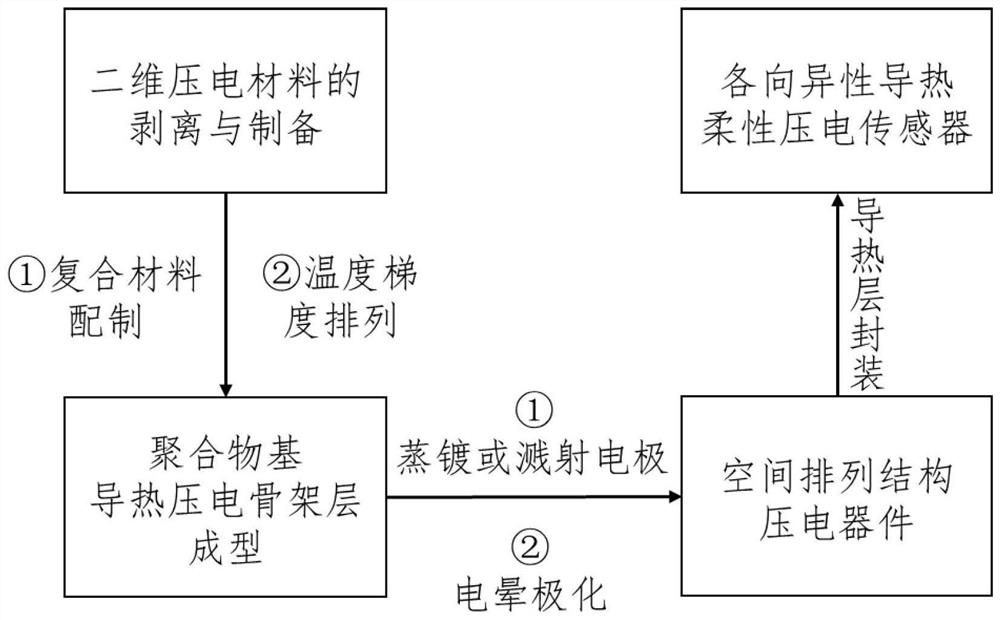
[0044] This example is to realize the molding of an anisotropically thermally conductive flexible piezoelectric sensor encapsulated with epoxy resin, using BNNS as piezoelectric material and PVA as polymer matrix. For the specific preparation process, refer to figure 1 , including the following steps:

[0045] The first step is to exfoliate to prepare 2D BNNS piezoelectric nanosheets

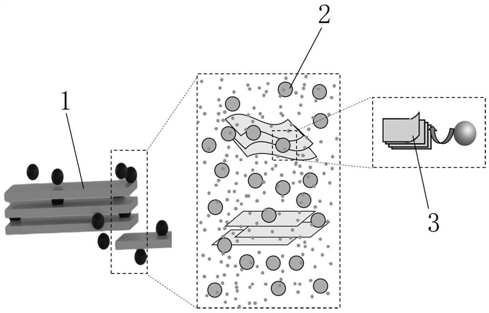
[0046] Principle of peeling method reference figure 2 . Take 4 g of h-BN raw material with a particle size of 13 μm, put it into a 1000 mL beaker, add 800 mL of N,N-dimethylformamide (DMF) to the beaker, and stir well with a glass rod to obtain a mass concentration of 5 mg / mL. dispersion system. It was placed in a cell disruptor, and was ultrasonically disrupted for 4 hours with a horn with a diameter of 20 mm under the parameter of an output power density of 80%. Subsequently, the colloid after ultrasonication was placed in a centrifuge at 2500 rpm for 25 minutes, and the supernatant was t...

Embodiment 2

[0058] This implementation case is to realize molybdenum disulfide (MoS) encapsulation with PDMS 2 ) The forming of the flexible piezoelectric sensor with anisotropic heat conduction in which the nanosheet is a piezoelectric material and TPU is a polymer matrix. For the specific preparation process, refer to figure 1 , including the following steps:

[0059] The first step is to exfoliate to prepare 2D MoS 2 Piezo Nanosheets

[0060] Take MoS with a particle size of 2 μm 2 4 g of raw materials were put into a 1000 mL beaker, 400 mL of deionized water and 400 mL of tert-butanol were added to the beaker, and a dispersion system with a mass concentration of 5 mg / mL was obtained after fully stirring with a glass rod. It was placed in a cell disruptor, and sonicated for 4 hours with a horn with a diameter of 20 mm under the parameter of an output power density of 60%. Subsequently, the colloid after ultrasonication was placed in a centrifuge at 2000 rpm for 25 minutes, and the ...

Embodiment 3

[0070] This example is to realize the molding of anisotropically thermally conductive flexible piezoelectric sensor encapsulated by PDMS, with BNNS as piezoelectric material and TPU-PVA composite material as polymer matrix. For the specific preparation process, refer to figure 1 , including the following steps:

[0071] The first step is to exfoliate to prepare 2D BNNS piezoelectric nanosheets

[0072] Take 4 g of h-BN raw material with a particle size of 13 μm, put it into a 1000 mL beaker, add 800 mL of N,N-dimethylformamide (DMF) to the beaker, and stir well with a glass rod to obtain a mass concentration of 5 mg / mL. dispersion system. It was placed in a cell disruptor, and was ultrasonically disrupted for 4 hours with a horn with a diameter of 20 mm under the parameter of an output power density of 80%. Subsequently, the colloid after ultrasonication was placed in a centrifuge at 2500 rpm for 25 minutes, and the supernatant was taken. The supernatant was poured into a v...


PUM

PropertyMeasurementUnit
thicknessaaaaaaaaaa
particle diameteraaaaaaaaaa

Abstract

An anisotropic heat-conducting flexible piezoelectric sensor and a preparation method thereof. The sensor as a whole is a sandwich structure, and from top to bottom are a directional heat-conducting encapsulation layer, an electrode layer, a heat-conducting piezoelectric skeleton layer, an electrode layer and a directional heat-conducting encapsulation layer, respectively. It has the characteristics of self-growth along the design direction, and the two-dimensional piezoelectric material BNNS or MoS contained in it 2 The nanosheets are arranged in the same direction in the polymer matrix polyurethane, polyvinyl alcohol or polydimethylsiloxane, and the arrangement direction is perpendicular to the direction of directional heat conduction; the preparation method includes: (1) exfoliation and preparation of the two-dimensional piezoelectric material; (2) thermally conductive piezoelectric skeleton layer temperature gradient arrangement molding; (3) preparation of spatially structured piezoelectric devices; (4) production of flexible piezoelectric sensors with anisotropic heat conduction; the advantages of the present invention are: higher mechanical Compared with flexible piezoelectric sensors prepared by traditional methods, they are more suitable for application in smart wearable electronic devices.

Description

technical field [0001] The invention is applicable to the technical fields of micro-nano composite material preparation and piezoelectric sensor preparation, and particularly relates to an anisotropic thermally conductive flexible piezoelectric sensor and a preparation method thereof. Background technique [0002] With the continuous development of electronic technology, traditional silicon-based electronic devices (silicon-based chips, silicon-based sensors, etc.) have developed to the physical limit described by Moore's Law, and it is difficult to make major technological breakthroughs in a short period of time. At the same time, due to the limitation of its intrinsic properties such as low toughness and brittle fracture, traditional silicon-based sensors are far from meeting the requirements of the increasingly emerging wearable electronic devices for stretchability and coverage. Therefore, flexible sensors have gradually become one of the hotspots in sensor research in r...

Claims


Application Information

Patent Timeline
Patent Type & Authority Patents(China)
IPC IPC(8): C08J9/36C23C14/34C23C14/24C23C14/20G01D5/12C08L75/04C08L29/04C08L83/04C08K3/38C08K3/30
CPCC08J9/365C23C14/34C23C14/24C23C14/205C23C14/20G01D5/12C08J2375/04C08J2329/04C08J2383/04C08J2475/04C08J2463/00C08J2483/04C08K2003/385C08K2003/3009C08K2201/011
Inventor 陈小明王春江宋启航徐超凡邵金友米翔宇田洪淼侯国珍
Owner XI AN JIAOTONG UNIV
Learn More