A box-combined transformer
A combined transformer and power transformer technology, applied in the field of transformers, can solve the problems of lack of height adjustment, poor cooling effect, water ingress, etc., and achieve the effects of improving cooling effect, improving practicability, and preventing damage.
- Summary
- Abstract
- Description
- Claims
- Application Information
AI Technical Summary
Problems solved by technology
Method used
Image
Examples
Embodiment 1
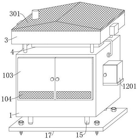
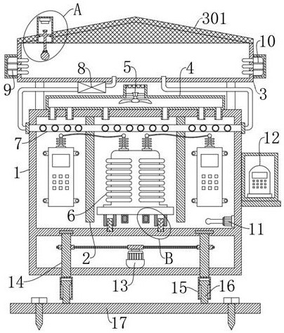
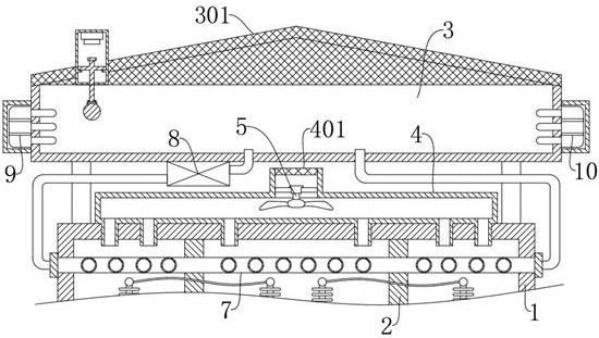
[0030] refer to Figure 1-7 , a sub-box combined transformer, including box 1, power transformer 6, high-voltage switchgear, low-voltage switchgear, box 1 is divided into three cavities by partition 2, high-voltage switchgear, power transformer 6, low-voltage switchgear The equipment is respectively arranged in three cavities, and also includes: a sump 3, which is fixedly connected to the upper end of the box body 1 through a support rod; a filter shed 301, which is fixedly connected to the sump pool 3; a diversion box 4, which is fixedly connected to the box body 1 Above, wherein, the air inlet of the splitter box 4 is fixedly connected with a suction fan 5 through a bracket, and the air outlet of the splitter box 4 is evenly distributed on the upper ends of the three cavities; And interspersed in the three cavities in turn, wherein, the water inlet and outlet of the return pipe 7 are respectively connected with the water inlet pipe and the water return pipe through the joint...
Embodiment 2
[0036] refer to figure 2 , a sub-box combined transformer, which is basically the same as that of Embodiment 1, furthermore: an electronic thermometer 11 is fixedly connected to the inside of the box body 1, and a control box 1201 is fixedly connected to one side of the box body 1, and the control box 1201 The main controller 12 is placed inside, and the electronic thermometer 11, the suction fan 5, the water pump 8, the refrigerator 9, and the heater 10 are all electrically connected with the main controller 12. Through the setting of the electronic thermometer 11, the The temperature in the box body 1 is transmitted to the main controller 12 in real time, and then analyzed by the main controller 12. When the temperature is too high, the suction fan 5, the water pump 8, and the refrigerator 9 can be controlled to work; when the temperature is low, the Control the suction fan 5, the water pump 8, and the heater 10 to work, thereby improving the automation of the sub-box combi...
Embodiment 3
[0038] refer to figure 1 and Figure 4 , a sub-box combined transformer, which is basically the same as Embodiment 1, furthermore: the box body 1 is rotatably connected with a box door 103 through a hinge, the box door 103 is provided with a heat dissipation port, and the heat dissipation port is fixedly connected with a The first dust-proof net 104, by setting the first dust-proof net 104 on the heat dissipation port of the box door 103, when the equipment in the box body 1 is ventilated, it can filter the dust and other fine impurities in the outside air to prevent them from entering Into the box 1, and attached to the equipment, affecting the heat dissipation effect of the equipment;
[0039] Both sides of the lower end of the power transformer 6 are rotatably connected with moving wheels 601. A chute matching the moving wheels 601 is provided in the box body 1. The lower end of the box body 1 close to the power transformer 6 is fixedly connected with a limit rod 101. A s...
PUM
 Abstract
Description
Claims
Application Information
 - R&D
- Intellectual Property
- Life Sciences
- Materials
- Tech Scout
- Unparalleled Data Quality
- Higher Quality Content
- 60% Fewer Hallucinations
Browse by: Latest US Patents, China's latest patents, Technical Efficacy Thesaurus, Application Domain, Technology Topic, Popular Technical Reports.
© 2025 PatSnap. All rights reserved.Legal|Privacy policy|Modern Slavery Act Transparency Statement|Sitemap|About US| Contact US: help@patsnap.com


