An energy-saving and environment-friendly recycled pulp drying device
A drying device, energy saving and environmental protection technology, applied in packaging recycling, pulp dewatering, packaging, etc., can solve the problems of troublesome operation, poor drying effect, etc., and achieve good drying effect.
- Summary
- Abstract
- Description
- Claims
- Application Information
AI Technical Summary
Problems solved by technology
Method used
Image
Examples
Embodiment 1
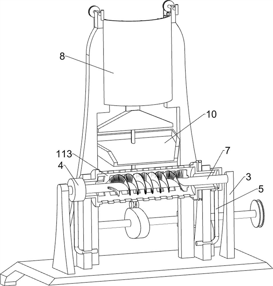
[0026] An energy-saving and environment-friendly recycled pulp drying device, such as figure 1 , figure 2 , Figure 4 and Figure 5 As shown, it includes a base 1, a support plate 2, a support plate 3, a hollow cylinder 4, a screw shaft 41, an air outlet pipe 5, a hot air blower 6, a vertical plate 7, a discharge cylinder 8, a hopper 9, an inclined frame 10, Collecting frame 101, conveying mechanism 11 and driving mechanism 12, a collecting frame 101 is placed in the middle of the left side of the top of the base 1, support plates 2 are fixed symmetrically on the front and rear sides of the top of the base 1, and four support plates 2 are arranged between the upper parts. Conveyor mechanism 11, drive mechanism 12 is provided between the front right part of the top of the base 1 and the conveying mechanism 11, the front and rear sides of the top of the base 1 are symmetrically fixed with support plates 3, and the top of the inner surface of the two support plates 3 on the le...
Embodiment 2
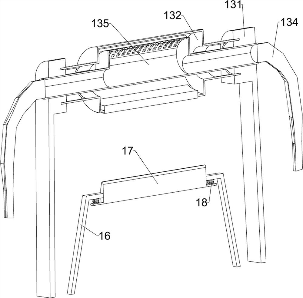
[0033] On the basis of Example 1, such as figure 1 , figure 2 , image 3 and Figure 6 As shown, a water absorbing mechanism 13 is also included, and the water absorbing mechanism 13 includes a bracket 131, a rotating cylinder 132, a sponge block 133, an outlet pipe 134 and an eccentric cylinder 135, and brackets 131 are evenly spaced in the middle of the front and rear sides of the top of the base 1 , there is a rotating cylinder 132 connected between the top of the inner surface of every two brackets 131 corresponding to the front and rear sides, and the middle part of the cylinder 132 is fixedly connected with sponge blocks 133 at uniform intervals in the circumferential direction. An eccentric cylinder 135 is fixedly connected between the upper parts of the brackets 131. The eccentric cylinder 135 is located in the drum 132. The eccentric cylinder 135 cooperates with the sponge block 133. Both ends of the eccentric cylinder 135 are fixedly connected with water outlet pi...
Embodiment 3
[0040] On the basis of embodiment 1 and embodiment 2, such as figure 2 and Figure 5 As shown, it also includes an n-type plate 16, a scraper 17 and a first spring 18. The n-type plate 16 is fixedly connected to the left side of the top of the base 1, and the upper middle of the n-type plate 16 is slidingly connected with a scraper 17. The top of the plate 17 is in contact with the grid conveyor belt 112 , and the first spring 18 is connected between the front and rear sides of the inner bottom of the scraper 17 and the inner top of the n-type plate 16 .
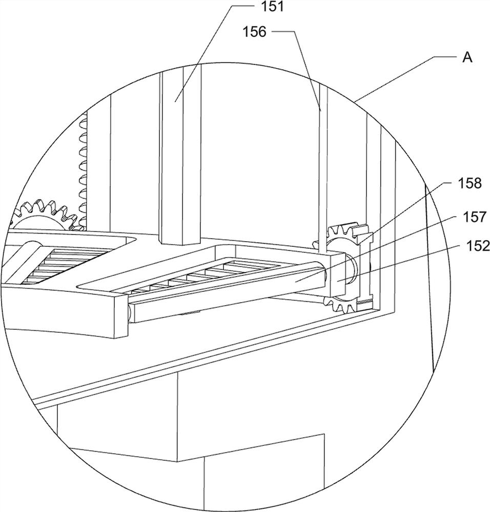
[0041] It also includes a limiting plate 19, a pedal 20 and a second spring 21, a sliding limit plate 19 is inserted in the middle of the left side of the top of the base, the limiting plate 19 is in contact with the collection frame 101, and the rear end of the limiting plate 19 is sliding. There is a pedal 20, and three second springs 21 are evenly spaced between the bottom left side of the limit plate 19 and the bottom ...
PUM
 Abstract
Description
Claims
Application Information
 - R&D
- Intellectual Property
- Life Sciences
- Materials
- Tech Scout
- Unparalleled Data Quality
- Higher Quality Content
- 60% Fewer Hallucinations
Browse by: Latest US Patents, China's latest patents, Technical Efficacy Thesaurus, Application Domain, Technology Topic, Popular Technical Reports.
© 2025 PatSnap. All rights reserved.Legal|Privacy policy|Modern Slavery Act Transparency Statement|Sitemap|About US| Contact US: help@patsnap.com


