Working method of textile yarn fixed-range traction device

A textile yarn and pulling device technology, which is applied in the continuous stretching and stretching processing of yarns, and in the field of textile yarn fixed-range pulling devices, can solve the problem of insufficient yarn pulling, excessive pulling, and unsatisfactory processing. Use and other issues to achieve the effect of reasonable structural design and improved automation

Inactive Publication Date: 2021-08-27
熊英姿
View PDF7 Cites 0 Cited by
  • Summary
  • Abstract
  • Description
  • Claims
  • Application Information

AI Technical Summary

Problems solved by technology

During the production and processing of yarn, it is necessary to pull and shape the bleached and dyed yarn, especially for the yarn with elastic texture. During the drawing process, it is difficult to quickly and smoothly pull the textile yarn back and forth, which affects the normal and stable drawing process of the yarn, and the existing pulling mechanism cannot conveniently and accurately adjust the yarn according to the type and specification of the textile yarn. The extent of the horizontal pulling of the yarn makes it difficult to accurately pull the yarn according to the needs, and it is easy to cause insufficient or excessive pulling of the yarn, which affects the quality of the normal pulling production and processing of the yarn, and cannot meet the requirements of processing and use. need

Method used


Image

  • Working method of textile yarn fixed-range traction device
  • Working method of textile yarn fixed-range traction device
  • Working method of textile yarn fixed-range traction device

Examples


Embodiment Construction

[0011] In order to further describe the present invention, a specific implementation of a textile yarn fixed-range pulling device will be further described below in conjunction with the accompanying drawings. The following examples are explanations of the present invention and the present invention is not limited to the following examples.

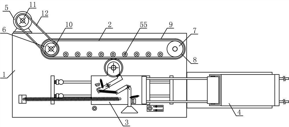
[0012] Such as figure 1 As shown, a textile yarn fixed-range pulling device of the present invention includes a reciprocating base 1, a driving mechanism 2, a reciprocating mechanism 3 and a yarn support mechanism 4, and the driving mechanism 2 and the reciprocating mechanism 3 are fixedly arranged on the reciprocating base in sequence along the horizontal direction 1 on the upper side, the yarn supporting mechanism 4 is vertically fixed on the reciprocating base 1 on one side of the reciprocating mechanism 3, and the driving mechanism 2 of the present invention includes a pulling motor 5, a driving shaft 6, an auxiliary rotating shaft 7 an...


PUM


Abstract

The invention discloses a working method of a textile yarn fixed-range traction device, and belongs to the field of textile processing mechanical equipment. A traction rack is arranged on the outer side of a traction belt, a traction motor and the traction belt are in transmission connection through a transmission belt, a reciprocating guide plate is arranged on a reciprocating guide rod in a sliding mode, a pulling plate gear is in meshed connection with the traction rack, a retreating tension spring is horizontally connected between the reciprocating guide plate and a reciprocating base, a yarn supporting connecting plate is vertically and fixedly arranged above the reciprocating guide plate along the forward stop lever side, the end portions of the upper side and the lower side of a traction support are horizontally and rotationally connected with a yarn inlet rotating roller and a yarn outlet rotating roller respectively, and an auxiliary traction rotating roller is horizontally arranged between an upper traction rotating roller and a lower traction rotating roller. The structural design is reasonable, textile yarn can be rapidly and stably subjected to traction processing, the horizontal traction amplitude can be adjusted according to the types and specifications of the textile yarn, the automation degree of yarn traction processing is increased, and the processing and using requirements are met.

Description

technical field [0001] The invention belongs to the field of textile processing machinery and equipment, and in particular relates to a working method of a fixed-range pulling device for textile yarns, which is mainly used in the continuous drawing and elongation processing of yarns. Background technique [0002] With the development of the production industry and the improvement of people's living standards, people have higher and higher requirements for textile materials. High-end textiles can be woven from high-quality textile materials to meet people's needs. Textile materials refer to fibers and fiber products, which are specifically manifested as fibers, yarns, fabrics and their composites. In modern textiles, the research and development of new textile materials, especially the development and use of nanofibers, has broken through the traditional textile materials. Conceptually, textile materials have become an important component of soft matter materials. Yarn is an...

Claims


Application Information

Patent Timeline
Patent Type & Authority Applications(China)
IPC IPC(8): D02J1/22
CPCD02J1/225
Inventor 熊英姿
Owner 熊英姿
Why Eureka
Try Eureka