
Inverter circuit, inverter control device, and vehicle drive device

A control device and inverter technology, applied in the direction of a stopped device, etc., can solve the problems of the inverter circuit temperature rising, the driver's burden becoming larger, and the vehicle cannot be driven, so as to reduce power consumption and improve redundancy. Effect

Pending Publication Date: 2021-08-27
NIPPON DENSAN CORP +1
View PDF6 Cites 0 Cited by
  • Summary
  • Abstract
  • Description
  • Claims
  • Application Information

AI Technical Summary

Problems solved by technology

As a result, during the parking lock process, a large current flows through the motor, causing problems such as temperature rise of the motor, temperature rise of the inverter circuit, and power consumption.
[0008] In addition, in an electric vehicle equipped with a parking lock control device described in Japanese Laid-Open Publication No. 2018-176832, etc., for example, when the parking lock mechanism does not operate due to a failure or the like, and the drive cannot be driven When the wheels are mechanically fixed, there is a problem that the vehicle cannot be stopped
[0009] In such a case, there is also a problem that, in order to maintain the stopped state of the vehicle, even if the vehicle is shifted to the parking lock, the driver needs to respond by operating the brake pedal, etc., and the burden on the driver becomes large.

Method used


Image

  • Inverter circuit, inverter control device, and vehicle drive device
  • Inverter circuit, inverter control device, and vehicle drive device
  • Inverter circuit, inverter control device, and vehicle drive device

Examples


no. 1 approach

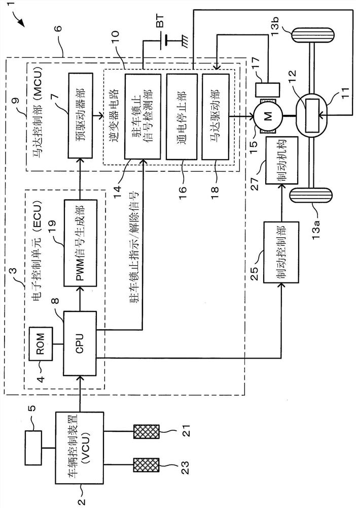
[0030] Hereinafter, embodiments of the present disclosure will be described in detail with reference to the drawings. figure 1 It is a block diagram showing the overall configuration of a vehicle such as an electric car equipped with the inverter circuit according to the first embodiment of the present disclosure.

[0031] exist figure 1 Among them, the vehicle 1 has the following parts: an electronic control unit (ECU: Electronic Control Unit) 3 as a motor control device; a vehicle control device (VCU: Vehicle Control Unit) as a higher-level control device (host controller) of the ECU 3 2. Motor control unit (MCU: Motor Control Unit) 9, which drives the electric motor 15 as the driving source of the vehicle 1 according to a control signal from the ECU 3; a transmission 11, which is connected to the electric motor 15, and the electric motor The rotational driving force of 15 is transmitted to the wheels 13a, 13b; and the parking lock mechanism 12 is built in the transmission ...

no. 2 approach

[0068] According to one aspect of the present disclosure, the parking lock function is realized by the motor control by the inverter circuit, thereby improving the redundancy of the parking lock function in the vehicle even when the mechanical parking lock function is not It is also possible to maintain the stopped state of the vehicle while working.

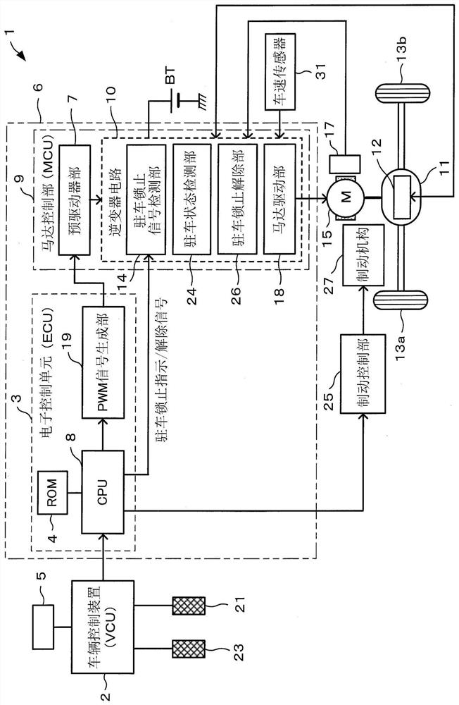
[0069] like figure 2 As shown, the inverter circuit 10 includes, in addition to the motor drive unit 18 , a parking lock signal detection unit 14 , a parking state detection unit 24 , a parking lock release unit 26 and the like which will be described later.

[0070] Therefore, when the parking lock signal detection unit 14 provided in the inverter circuit 10 in the MCU 9 is Figure 5 When the parking lock instruction signal transmitted from the VCU 2 via the ECU 3 is detected in step S111, in step S113, it is determined whether or not a predetermined hill holding condition is satisfied.

[0071] As hill holding conditions, f...


PUM


Abstract

The invention provides an inverter circuit, an inverter control device, and a vehicle drive device. An inverter circuit for driving an electric motor, which is a drive source of a vehicle, is provided with: a parking lock instruction detection unit for detecting a parking lock instruction for suppressing rotation of drive wheels of the vehicle; and an energization stopping unit that stops the drive current to the electric motor when the parking lock instruction is detected. Alternatively, the inverter circuit that drives an electric motor, which is a drive source of a vehicle, is provided with: a parking lock instruction detection unit that detects a parking lock instruction that suppresses rotation of drive wheels of the vehicle; a rotation angle detection unit that detects a rotor rotation angle of the electric motor; and a control unit that, when the parking lock instruction is detected, controls the electric motor such that the rotor rotation angle becomes a constant value or less.

Description

technical field [0001] The present disclosure relates to an inverter circuit, an inverter control device, and a vehicle drive device that supply driving power to a motor mounted on a vehicle or the like. Background technique [0002] As vehicles such as electric vehicles and hybrid vehicles using motors as the drive source become more sophisticated, the inverters that supply electric power to the motors and their control circuits are required to be highly functional. In these vehicles, an electronic control unit (ECU: Electronic Control Unit) determines the running state of the vehicle, the driving operation state of the driver, and the like based on detection signals from various sensors and signals from an on-vehicle device. [0003] Generally, a vehicle is provided with a parking lock mechanism that prevents rotation of an axle when the vehicle is parked. Also in an electric vehicle or the like, the tire is mechanically fixed by engaging a lock pin with a gear or the lik...

Claims


Application Information

Patent Timeline
Patent Type & Authority Applications(China)
IPC IPC(8): B60W10/18B60W10/188B60W10/192B60W10/196H02P6/24
CPCB60W10/182B60W10/192B60W10/188B60W10/196H02P6/24
Inventor 中田雄飞小池上贵三本松功向山浩司
Owner NIPPON DENSAN CORP
Learn More