
VOCs waste gas treatment equipment

A waste gas treatment equipment, waste gas technology, applied in gas treatment, lighting and heating equipment, air quality improvement and other directions, can solve the problems of large VOCs waste gas, affecting VOCs waste gas treatment efficiency, long recovery time, etc., to achieve efficient and balanced recovery Activity, reduce activity recovery time, and ensure the effect of absorption efficiency

Pending Publication Date: 2021-08-27
杭州泉尚环境科技有限公司
View PDF3 Cites 0 Cited by
  • Summary
  • Abstract
  • Description
  • Claims
  • Application Information

AI Technical Summary

Problems solved by technology

[0004] It can be seen from the above that in various industrial production links, it is very necessary to treat VOCs exhaust gas. It is a relatively common method to use activated carbon for VOCs exhaust gas absorption, but the activated carbon arranged in the ventilation pipe is used for VOCs exhaust gas absorption. At the same time, the activated carbon in the front end first contacts the VOCs exhaust gas, and the activated carbon in the middle and rear stages contacts the subsequent VOCs exhaust gas that is not absorbed by the front-end activated carbon, resulting in a greater degree of VOCs exhaust gas absorbed by the activated carbon in the front stage than in the middle and rear stages.
[0005] However, after the activated carbon has been absorbed for a certain period of time, if it is heated to restore its activity, the activated carbon in the previous stage will be too saturated due to the degree of adsorption, and it will take a long time for the activity to recover.
If activated carbon activity recovery is carried out in a non-replaceable structure in the device, it will affect the efficiency of VOCs exhaust gas treatment

Method used


Image

  • VOCs waste gas treatment equipment
  • VOCs waste gas treatment equipment
  • VOCs waste gas treatment equipment

Examples


Embodiment 1

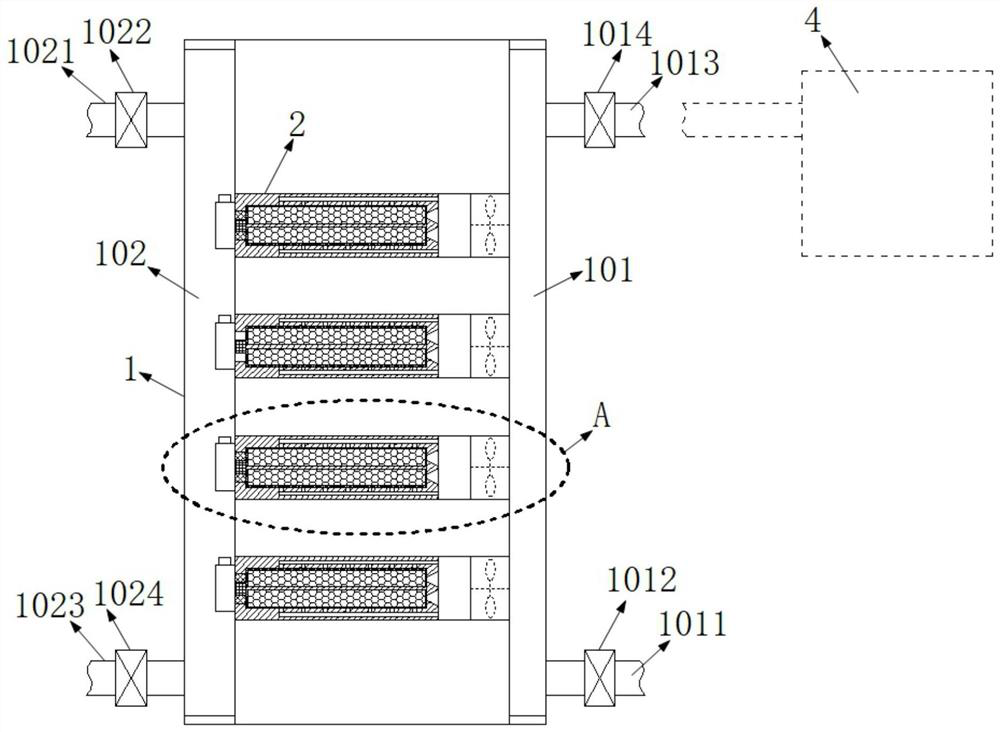
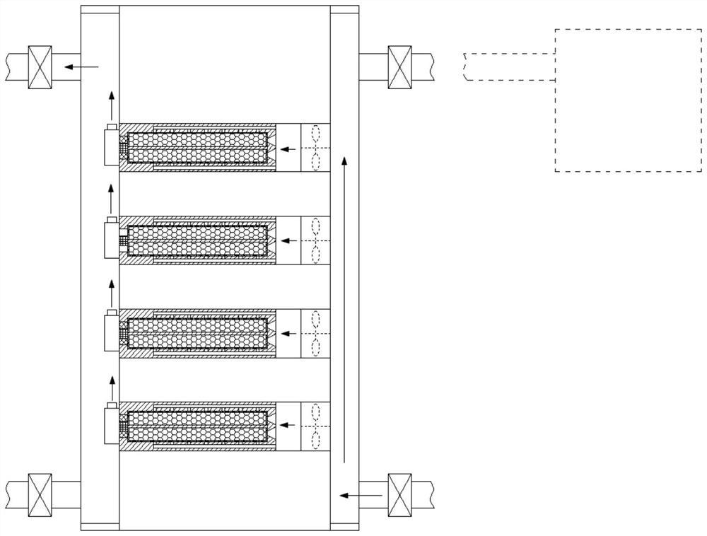
[0052] The waste gas absorbing device 1 includes a waste gas inlet channel 101 and a waste gas outlet channel 102 . One side of the waste gas absorbing device 1 is communicated with a first intake pipe 1011 .

[0053] The first air intake pipe 1011 is provided with an intake electromagnetic valve 1012 , and the other side of the waste gas absorption device 1 is connected with a first air outlet pipe 1021 , and the first air outlet pipe 1021 is connected with the waste gas outlet channel 102 .

[0054] The first intake pipe 1011 is provided with an intake solenoid valve 1012 , and the backflow outlet pipe 1013 is provided with a backflow solenoid valve 1014 .

[0055] The first air outlet pipe 1021 is equipped with an air outlet solenoid valve 1022 , and the backflow inlet pipe 1013 is equipped with a ventilation solenoid valve 1024 .

[0056] One side of the waste gas absorption device 1 is provided with a backflow inlet pipe 1013 connected with the exhaust gas outlet channel ...

Embodiment 2

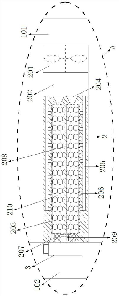
[0058] Exhaust gas absorbing device 1 is provided with a number of exhaust gas absorbing horizontal pipes 2 located between the exhaust gas inlet channel and the exhaust gas outlet channel 102. The exhaust gas absorbing horizontal tube 2 includes a negative pressure fan 201, and the negative pressure fan 201 communicates with the exhaust gas inlet channel 101. The exhaust gas absorption horizontal pipe 2 includes a negative pressure inner chamber 202, which is adjacent to the negative pressure fan 201, and the exhaust gas absorption horizontal pipe 2 includes an activated carbon mesh cover 203, and the activated carbon mesh cover 203 is filled with internal activated carbon 210.

[0059] In the waste gas absorption horizontal pipe 2, a shell structure surrounding the periphery of the activated carbon mesh cover 203 is arranged. A first main port 204 is opened on one side of the shell structure, and the first main port 204 communicates with the activated carbon mesh cover 203. T...

Embodiment 3

[0064] The VOCs waste gas treatment equipment includes a control platform, which is equipped with a main processing controller. The main processing controller communicates with the peripheral ventilation solenoid valve 3, intake solenoid valve 1012, return flow solenoid valve 1014, outlet solenoid valve 1022, The ventilation solenoid valve 1024, the heating rod 208, the negative pressure fan 201 and the organic gas combustion furnace 2 are connected, and the main processing controller is connected with the temperature sensing module 209 through a data line.


PUM


Abstract

The invention discloses VOCs waste gas treatment equipment, and relates to the technical field of VOCs waste gas treatment. A negative pressure fan communicated with a waste gas inlet channel is arranged at one end of a waste gas absorption transverse pipe; a negative pressure inner cavity adjacent to the negative pressure fan is arranged in the waste gas absorption transverse pipe; an activated carbon mesh enclosure is filled with internal activated carbon; a peripheral ventilation electromagnetic valve located at the position of a second main port of the waste gas absorption transverse pipe is arranged in a waste gas outlet channel. A heating rod used for heating internal activated carbon is arranged in the activated carbon mesh enclosure, and a temperature sensing module used for sensing and monitoring the temperature of a heating rod is arranged on one side of the activated carbon mesh enclosure. The VOCs waste gas is prevented from being absorbed by internal activated carbon in the front-end area in a supersaturated mode, the relative adsorption degree of activated carbon particles in the middle-rear section is low, when the activity of the activated carbon in the waste gas absorption transverse pipe is recovered, the activity can be efficiently recovered in a balanced mode due to balanced absorption, and the activity recovery time of the internal activated carbon is shortened.

Description

technical field [0001] The invention belongs to the technical field of VOCs waste gas treatment, and in particular relates to a VOCs waste gas treatment equipment. Background technique [0002] According to the definition of the World Health Organization (WHO), VOCs (volatile organic compounds) are various organic compounds with a boiling point of 50°C to 260°C at room temperature. In my country, VOCs refer to organic compounds with a saturated vapor pressure greater than 70Pa at room temperature and a boiling point below 260°C at normal pressure, or all organic compounds with a vapor pressure greater than or equal to 10Pa at 20°C and are volatile. [0003] Most VOCs have unpleasant special smell, and are toxic, irritating, teratogenic and carcinogenic, especially benzene, toluene and formaldehyde will cause great harm to human health. VOCs are important precursors that cause urban haze and photochemical smog, mainly from coal chemical industry, petrochemical industry, fuel...

Claims


Application Information

Patent Timeline
IPC IPC(8): B01D53/04F23G5/50F23G7/06
CPCB01D53/0407B01D53/0438B01D53/0454F23G7/06F23G5/50B01D2253/102B01D2257/708B01D2259/40088F23G2209/14Y02A50/20
Inventor 洪志平王欣顾伟顾皛鑫王勇洪敏
Owner 杭州泉尚环境科技有限公司
Learn More