Method for preparing hollow integral structure by using pipes

An overall structure, hollow technology, applied in the direction of mechanical equipment, engine components, etc., can solve the problems of increasing the number and complexity of hot pressing molds, and achieve the effect of reducing the difficulty of processing technology, avoiding the defects of gas ports between core plates, and being easy to achieve

Active Publication Date: 2021-08-24
NANJING UNIV OF AERONAUTICS & ASTRONAUTICS
View PDF11 Cites 0 Cited by
  • Summary
  • Abstract
  • Description
  • Claims
  • Application Information

AI Technical Summary

Problems solved by technology

This invention avoids the problem of precise forming of the inner cavity of the multi-layer hollow structure and the problem that different materials cannot be used for the inner and outer layers, but this method makes the number and complexity of the hot pressing molds increase with the increase of the type and complexity of the core board

Method used


Image

  • Method for preparing hollow integral structure by using pipes
  • Method for preparing hollow integral structure by using pipes
  • Method for preparing hollow integral structure by using pipes

Examples


Embodiment 1

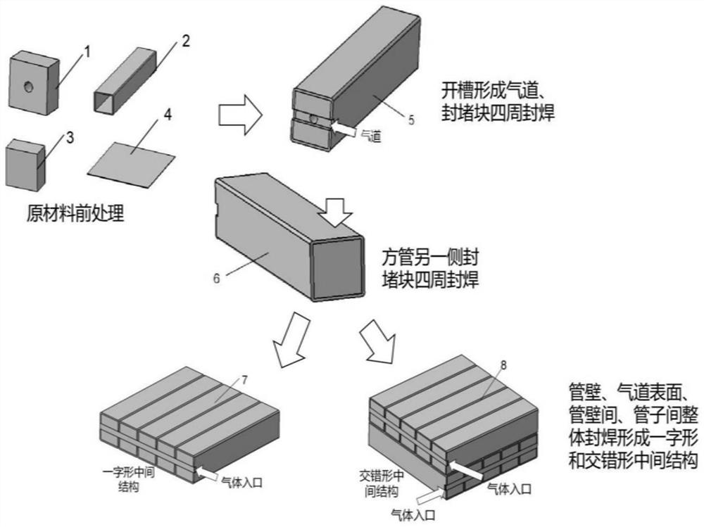
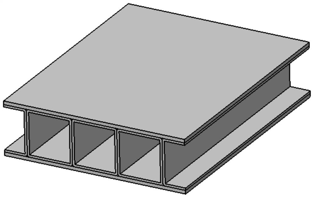
[0064] Example as Figure 1-8 As shown, the hollow structure includes at least one layer of a tube array, the tube array includes a number of tubes 2 parallel to each other and closely arranged in sequence, and the upper and lower sides of the tube array are provided with panels 4 with flat panels. 4. It is fixedly connected to several tubes 2 in the tube array; because the structure is tube 2 before forming, it can reduce the superplastic forming process of the core board, and can directly heat and pressurize the diffusion, which can reduce the difficulty of the processing technology and avoid the use of existing There are defects such as gas port defects between core plates caused by the multi-layer plate forming process, diffusion welding defects between core plates, and the inability of the core plates to fully expand to form a rectangular cross-sectional shape.

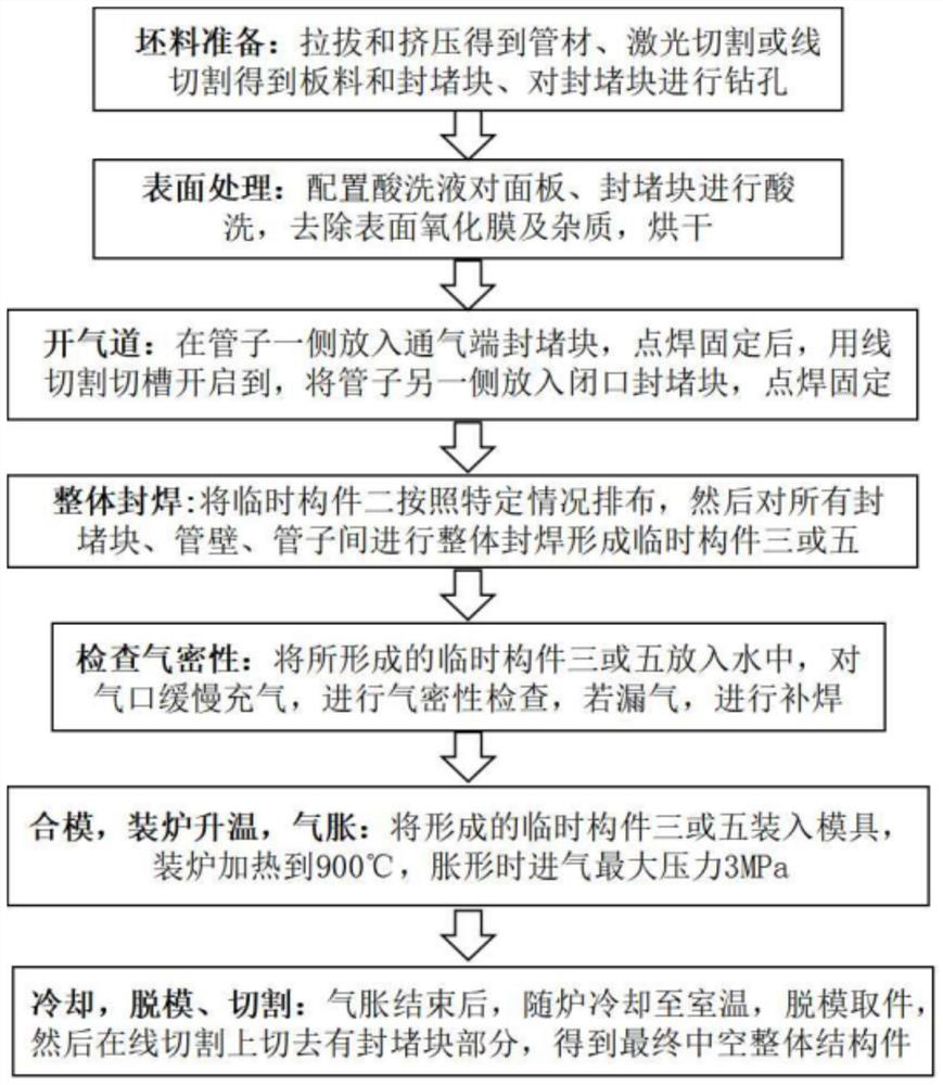
[0065] When the panel is a flat plate, the hollow structure is prepared as follows:

[0066] S1 blank prepara...

Embodiment example 2

[0100] Implementation case two such as figure 1 and 9 As shown in -12, the tube array includes a number of tubes 2 that are parallel to each other and closely arranged in sequence. The inner and outer sides of the tube array are provided with cylindrical thin-walled panels 9 whose panels are cylindrical thin-walled tubes. The thin-walled panel 9 is fixedly connected to several tubes 2 in the tube array; because the structure is a tube structure before forming, the superplastic forming process of the core plate can be reduced, and the direct heating and pressure diffusion can be performed, which can reduce the difficulty of the processing technology and avoid the The existing multi-layer board forming process causes the defects of air ports between the core boards, the diffusion welding defects between the core boards, and the inability of the core boards to fully expand to form a rectangular cross-sectional shape and other defects.

[0101] When the panel is a cylindrical thi...


PUM


Abstract

The invention discloses a method for preparing a hollow integral structure by using pipes, and relates to the field of metal structural part machining methods. The preparation method is simple in steps, high in machining efficiency and low in machining cost, and the machined hollow structure has higher structural strength, so that the pipe superplastic forming diffusion bonding hollow structure meets the requirements for weight reduction, high strength, vibration reduction, energy absorption and the like. The preparation method comprises the steps of 1, preparing a blank; 2, carrying out surface treatment; 3, opening an air passage; 4, carrying out sealing and welding; 5, checking the air tightness; 6, closing a die and carrying out charging, heating and inflating; and 7, carrying out cutting. According to the scheme, the arrangement structure of the pipes is regular and simple and easy to achieve, the machining process difficulty is reduced, and the overall structural strength and impact resistance are good.

Description

technical field [0001] The invention relates to the field of processing methods for metal structural parts, in particular to a processing method for connecting metal pipes and panels of the same material under high temperature by gas pressure diffusion. Background technique [0002] At present, in order to achieve the purpose of reducing weight, improving structural strength, and absorbing vibration and energy, complex hollow multi-layer structures are widely used in aviation, aerospace, automotive and other fields. In the aerospace field, the complex hollow multi-layer titanium plate structure generally adopts the process method of stamping and welding, and the process is complicated and the forming quality is unstable. Superplastic forming / diffusion joining technology combines forming and diffusion joining processes to form large and complex integral components at one time, with stable and reliable quality, significant weight reduction and improved component performance. ...

Claims


Application Information

Patent Timeline
IPC IPC(8): B21K1/14
CPCB21K1/14
Inventor 武永陈金阳陈明和谢兰生
Owner NANJING UNIV OF AERONAUTICS & ASTRONAUTICS
Why Eureka
Try Eureka