
Medical implant and manufacturing method thereof

A manufacturing method and implant technology, applied in the field of medical devices, can solve the problems of not being able to fully conform to the shape of the aneurysm, not being able to completely embolize the aneurysm, etc.

Pending Publication Date: 2021-08-24
SHANGHAI VASOLUTIONS MEDTECH CO LTD
View PDF0 Cites 1 Cited by
  • Summary
  • Abstract
  • Description
  • Claims
  • Application Information

AI Technical Summary

Problems solved by technology

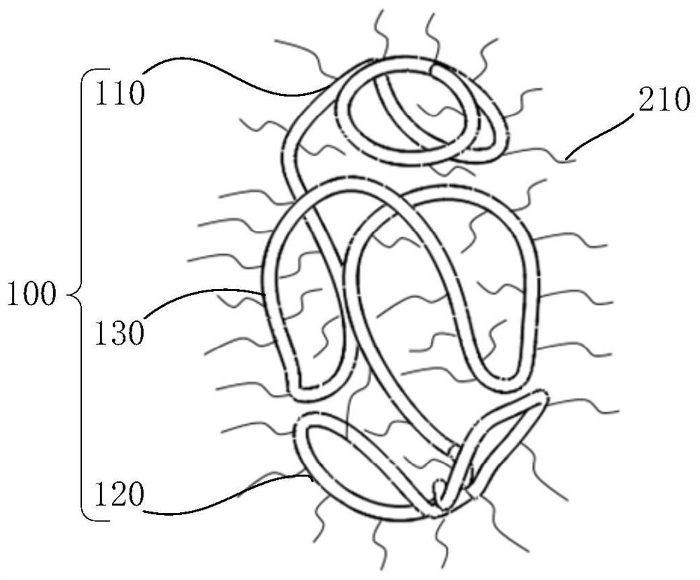
However, the end profile of the existing three-dimensional structure of the coil is a planar structure, which cannot fully conform to the shape of the aneurysm, resulting in the inability of the coil system to completely embolize the aneurysm

Method used


Image

  • Medical implant and manufacturing method thereof
  • Medical implant and manufacturing method thereof
  • Medical implant and manufacturing method thereof

Examples


Embodiment 1

[0062] First, a metal wire with a diameter of 0.5 mm to 2 mm is helically wound along a mandrel to form a cylindrical helical spring structure, and then the mandrel is pulled away to obtain a primary coil 10 (such as Figure 4 shown).

[0063] Next, a mold 20 is provided, and the mold 20 includes a main body 21 and a boss 22 . In this embodiment, the main body 21 includes a cylinder 21a and a first hemisphere 21b and a second hemisphere 21c respectively disposed at two ends of the cylinder 21a. The cross-section of the protruding posts 22 is circular, and the number of the protruding posts 22 is ten, wherein three of the protruding posts 22 are evenly arranged around the axis of the first hemispherical body 21b, and four of the protruding posts 22 are arranged uniformly around the axis of the first hemisphere 21b. Columns 22 are evenly arranged around the axis of the cylinder 21a, and the remaining three convex columns 22 are evenly arranged around the axis of the second hemisp...

Embodiment 2

[0070] The difference between this embodiment and the first embodiment lies in that the number and arrangement of the protrusions 22 on the mold 20 are different. Specifically, please refer to Figure 11 , the mold 20 includes sixteen bosses 22, three of which are evenly arranged around the axis of the first hemisphere 21b, and three of the bosses 22 are arranged around the axis of the second hemisphere The axes of 21c are evenly arranged, and the remaining ten bosses 22 are divided into a first boss group and a second boss group, each group including five bosses 22 . The first protruding post group is close to the first hemispherical body 21b, and the five protruding posts 22 in this group are uniformly arranged around the circumference of the cylinder 21a. The second protruding post group is close to the second hemispherical body 21c, and the five protruding posts 22 in this group are uniformly arranged around the circumference of the cylinder 21a. In the circumferential d...


PUM


Abstract

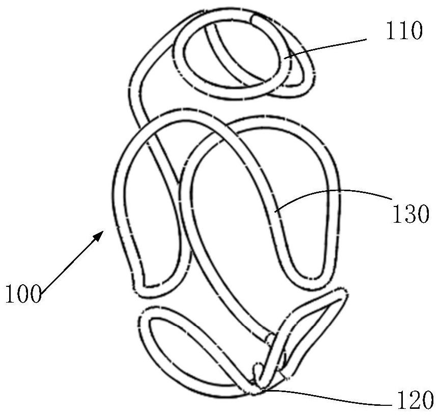
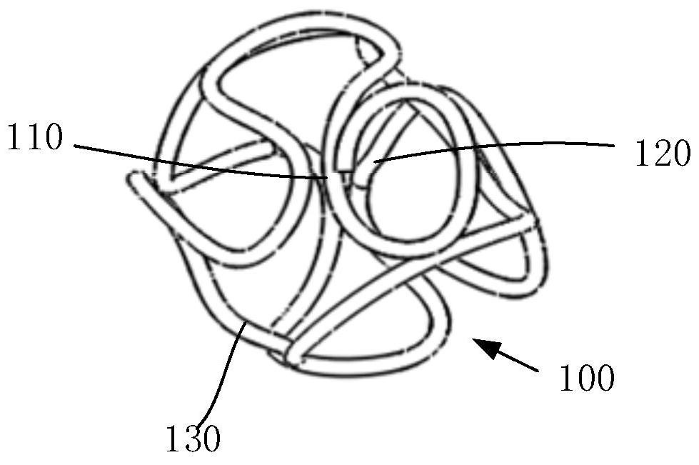
The invention provides a medical implant and a manufacturing method thereof. The medical implant comprises a spring ring, the spring ring comprises a first spring ring unit and a second spring ring unit, and the first spring ring unit is connected with the second spring ring unit; the outer surface of the first spring ring unit is located on a first curved surface, and the concave side of the first curved surface is arranged towards the second spring ring unit. The medical implant is used for blocking treatment of hemangioma, the first spring ring unit can adapt to the shape of the tumor wall of the hemangioma, the compactness of intra-tumor embolism is improved, and the treatment effect is improved.

Description

technical field [0001] The invention relates to the technical field of medical devices, in particular to a medical implant and a manufacturing method thereof. Background technique [0002] Aneurysm is a localized bulging or fusiform dilated lesion due to arterial wall disease or injury, which has a serious impact on the health of patients. With the development of imaging technology and intravascular biomaterials, endovascular interventional therapy has become the first choice for the treatment of aneurysms because it has less risk and trauma than surgical treatment. [0003] Aneurysm embolization coils are currently the main method for treating aneurysms. In the process of coil embolization of aneurysms, the coils expand into a predetermined shape in the aneurysm and achieve corresponding embolization effects. In order to fit the coils to and occlude different sized vascular structures, the coils may have different shapes and / or different cross-sectional diameters. In use,...

Claims


Application Information

Patent Timeline
IPC IPC(8): A61B17/12
CPCA61B17/12113A61B17/12145A61B17/1215A61B2017/00526
Inventor 张广建杨波王洪杰刘梦钦郭澜涛苗铮华
Owner SHANGHAI VASOLUTIONS MEDTECH CO LTD
Learn More