
Narrow-window coaxial single-line laser scanning range finder

A technology of laser scanning distance measurement and laser distance measurement, which is applied in the field of laser scanning, and can solve problems affecting the integrity of intelligent robots, complex structures, and large effective optical window heights

Pending Publication Date: 2021-08-20
SHANGHAI SLAMTEC
View PDF7 Cites 1 Cited by
  • Summary
  • Abstract
  • Description
  • Claims
  • Application Information

AI Technical Summary

Problems solved by technology

However, this void space will affect the overall perception of the intelligent robot. The greater the height of the space, the worse the visual perception and the greater the difficulty of the design
[0004] At present, the laser scanning rangefinder based on the principle of time-of-flight ranging, because the distance measuring module and the scanning module are separated, the scanning module is usually composed of a mirror, and in order to make the outgoing laser in a horizontal direction, the mirror is often arranged at 45° Angle oblique setting, the overall height of the reflector will therefore reach about 1.4 times the size of the receiving lens aperture, which will make the effective optical window height of the entire device larger
If it is installed on the moving chassis of the robot, it is necessary to leave a large gap between the moving chassis of the robot and the application layer, which is obviously not conducive to the integrated appearance of the robot
[0005] Not only that, the scanning module composed of mirrors often has a complex structure, difficult process, and many assembly steps, resulting in extremely low mass production yield, which is not conducive to mass application

Method used


Image

  • Narrow-window coaxial single-line laser scanning range finder
  • Narrow-window coaxial single-line laser scanning range finder
  • Narrow-window coaxial single-line laser scanning range finder

Examples


Embodiment Construction

[0052] The following will clearly and completely describe the technical solutions in the embodiments of the application with reference to the drawings in the embodiments of the application. Apparently, the described embodiments are only some of the embodiments of the application, not all of them. Based on the embodiments in this application, all other embodiments obtained by persons of ordinary skill in the art without making creative efforts belong to the scope of protection of this application.

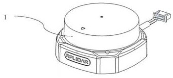
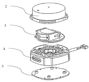
[0053] Such as figure 1 and figure 2 As shown, in one of the embodiments of the present application, a narrow-window coaxial single-line laser scanning rangefinder includes:

[0054] A ranging core component 3, which is used to obtain ranging data;

[0055] A control module 4, which is used to provide a rotational driving force, the control module 4 is movably connected with the distance measuring core 3 and drives the distance measuring core 3 to realize 360° scanning;

[0056]...


PUM


Abstract

The invention discloses a narrow-window coaxial single-line laser scanning range finder, and the range finder comprises: a range finding core part which is used for obtaining range finding data; a control module which is movably connected with the range finding core part; and a ranging core part which comprises an optical module and an information processing module, wherein the information processing module is used for processing a laser ranging signal obtained by the optical module and converting the laser ranging signal into distance data. The optical module comprises a laser emitting unit, a focusing lens and a photosensitive receiving unit. The laser emitting unit is used for generating pulse emitting laser and generating a start signal used for flight time timing. The focusing lens is used for converging the light beams reflected by the measured object and focusing the light beams to the photosensitive receiving unit; and the photosensitive receiving unit is used for generating a photoelectric signal and generating a stop signal for timing in flight according to the photoelectric signal. According to the invention, the ranging core member is rotatably arranged on the control module, 360-degree scanning ranging can be realized, a reflector device is omitted, the process difficulty of assembly is reduced, and the yield of mass production can be effectively improved.

Description

technical field [0001] The application belongs to the technical field of laser scanning, and in particular relates to a narrow-window coaxial single-line laser scanning rangefinder. Background technique [0002] As a high-precision ranging solution, laser scanning ranging technology is more and more widely used in autonomous positioning and navigation services of intelligent robots and for unfamiliar Environment recognition and environment map construction. [0003] In order to take into account positioning navigation and intelligent obstacle avoidance at the same time, the laser scanning rangefinder used for intelligent robots is often placed on the motion control module of the robot. Application layer, such as distribution layer, guidance layer, patrol layer, etc. Therefore, a certain height gap space needs to be set between the application layer and the moving chassis for the laser scanning rangefinder to project the beam and receive the reflected light signal. However...

Claims


Application Information

Patent Timeline
Patent Type & Authority Applications(China)
IPC IPC(8): G01S17/10G01S7/481
CPCG01S7/481G01S7/4817G01S17/10
Inventor 黎龙飞雷乔夏吴斌施玲玲于远芳陈士凯
Owner SHANGHAI SLAMTEC
Learn More