
Afterburner structure based on self-excitation sweeping oscillation fuel nozzle

A technology of afterburner and fuel nozzle, applied in the direction of combustion chamber, continuous combustion chamber, combustion method, etc., can solve problems such as uneven distribution of fuel space, requirements for reducing the length of afterburner, difficult design goals, etc., to achieve Effects of improving combustion efficiency and combustion instability, shortening length, improving atomization performance and spatial distribution uniformity

Active Publication Date: 2021-08-20
AERO ENGINE ACAD OF CHINA
View PDF22 Cites 11 Cited by
  • Summary
  • Abstract
  • Description
  • Claims
  • Application Information

AI Technical Summary

Problems solved by technology

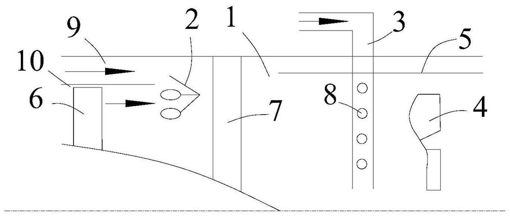
However, if the traditional direct injection fuel nozzle is still used in the afterburner and the sub-combustion ram combustor, although its structure is simple, the spatial distribution of the injected fuel is extremely uneven, which will seriously affect the combustion efficiency; at the same time As a result, the flow distance for atomization and mixing in the high-speed transverse airflow is too long, which makes it difficult to further reduce the length of the afterburner for the next-generation engine; at the same time, the inlet temperature of the next-generation afterburner is higher, and the spontaneous combustion is delayed. The time is shorter, and the good atomization, evaporation and mixing of fuel must be completed within 50mm to avoid spontaneous combustion of fuel. It is difficult to achieve the above design goals with ordinary direct injection fuel nozzles

Method used


Image

  • Afterburner structure based on self-excitation sweeping oscillation fuel nozzle
  • Afterburner structure based on self-excitation sweeping oscillation fuel nozzle
  • Afterburner structure based on self-excitation sweeping oscillation fuel nozzle

Examples


Embodiment Construction

[0037]The present invention will be further described in detail below in conjunction with the accompanying drawings and embodiments. It can be understood that the specific implementation manners described here are only used to explain relevant content, rather than to limit the present invention. In addition, it should be noted that, for the convenience of description, only the parts related to the present invention are shown in the drawings.

[0038] It should be noted that, in the case of no conflict, the embodiments and features in the embodiments of the present invention can be combined with each other. The present invention will be described in detail below with reference to the drawings and in combination with embodiments.

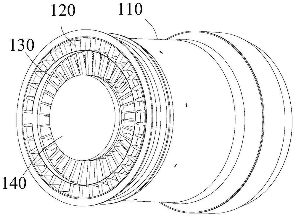
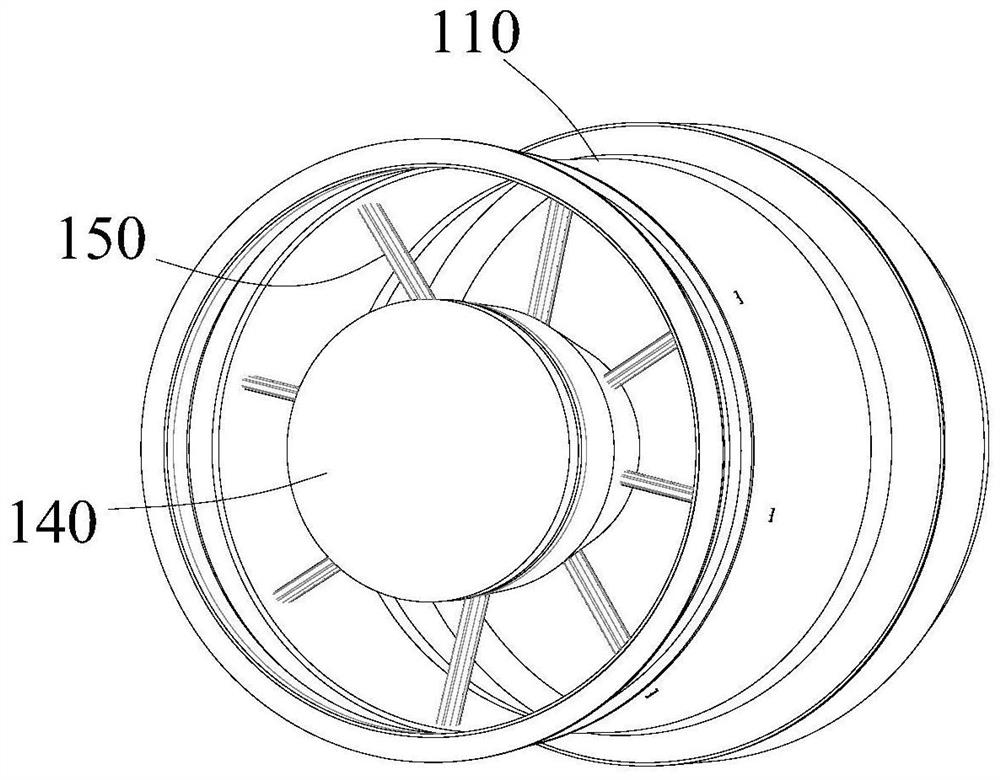
[0039] See attached figure 2 and attached Figure 4 , the present invention firstly discloses an afterburner structure based on a novel fuel nozzle 152 . The engine includes a casing 110 , an outer turbine 120 , an inner turbine 130 and a central...


PUM


Abstract

The invention provides an afterburner structure based on a self-excitation sweeping oscillation fuel nozzle. According to the fuel nozzle, under the condition of stable inlet fuel flow, the coanda effect of the fluid and the alternating feedback effect of the feedback channel, sweeping type oscillating jet flow with a certain frequency is formed at an outlet, so that the space uniformity of fuel injection is improved, on the basis that the structural complexity of an afterburner of an existing turbine engine and a ramjet combustion chamber of a subsonic combustion ramjet engine is not increased, the atomization performance and the oil-gas mixing uniformity of fuel oil in the afterburner / ramjet combustion chamber can be greatly improved, the combustion efficiency and the combustion instability of the engine are improved, meanwhile, the lengths of the afterburner and the subsonic combustion ramjet combustion chamber are shortened.

Description

technical field [0001] The invention belongs to the technical field of fuel injection and structural design of aero-engines, and in particular relates to fuel injection and structural forms in afterburning chambers. Background technique [0002] Certain aeroengines may not perform well across the entire thrust range. For example, when an aircraft takes off, it needs a lot more thrust than when it is cruising. If the engine is designed according to the take-off thrust, the mass of the engine will be too large, and the engine will be in a non-design point state during cruising, and the performance will be very poor; If the engine is not designed for thrust, it will cause the aircraft to fail to take off normally. One of the measures to solve the above problems is to add an afterburner between the gas turbine and the nozzle of the engine to greatly increase the engine thrust in a short time. Although the mass of the afterburner is only about 1 / 5 of the engine, the thrust can ...

Claims


Application Information

Patent Timeline
Patent Type & Authority Applications(China)
IPC IPC(8): F23R3/28
CPCF23R3/286Y02T50/60F23R3/20F02K3/10F05D2240/36F23D2900/14482
Inventor 王士奇温泉韩啸
Owner AERO ENGINE ACAD OF CHINA
Learn More