
Method and device for treating tunnel secondary lining vault cavity and local loose part

A technology for tunnels and cavities, which is applied in the direction of tunnel lining, tunnel lining, shaft lining, etc. It can solve the problems of time-consuming, labor-intensive, high investment cost, and difficult construction.

Pending Publication Date: 2021-08-20
NO 1 ENG CO LTD OF FHEC OF CCCC
View PDF0 Cites 2 Cited by
  • Summary
  • Abstract
  • Description
  • Claims
  • Application Information

AI Technical Summary

Problems solved by technology

After the formation of the second lining concrete, voids and loose cement layers will be formed between the outer cement layer of the arch and the waterproof board, especially the voids and loose cement layers on the outer side of the vault, which will affect the construction quality of the tunnel lining
Therefore, it is necessary to backfill the cement slurry treatment to the voids and the undense parts of the cement layer. The conventional treatment method is to drill holes at the second lining concrete at the lower end of the vault voids and undense areas to communicate with the vault voids and undense areas, and then Inward grouting to close the vault cavity and the undense structure, but this method is not only time-consuming and laborious, high investment cost, long construction period, not easy to construct, but also often punctures the waterproof board or exists in the cavity during grouting. Insufficiency of gas pressure affecting grouting effect

Method used


Image

  • Method and device for treating tunnel secondary lining vault cavity and local loose part
  • Method and device for treating tunnel secondary lining vault cavity and local loose part
  • Method and device for treating tunnel secondary lining vault cavity and local loose part

Examples


Embodiment Construction

[0054] In order to make the technical means, creative features, goals and effects achieved by the present invention easy to understand, the present invention will be further elaborated below in conjunction with specific embodiments, but the following embodiments are only preferred embodiments of the present invention, not all. Based on the examples in the implementation manners, other examples obtained by those skilled in the art without making creative efforts all belong to the protection scope of the present invention. The experimental methods in the following examples, unless otherwise specified, are conventional methods, and the materials, devices, equipment, reagents, etc. used in the following examples, unless otherwise specified, can be obtained from commercial sources.

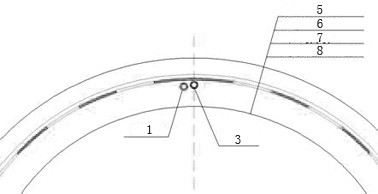
[0055] like Figure 1 to Figure 6 As shown, a device for treating the cavity and local loose part of the second lining of the tunnel is composed of a waterproof board, and also includes a longitudinal ...


PUM


Abstract

The invention belongs to a method and a device for treating a tunnel secondary lining vault cavity and a local loose part, and the device is characterized in that three slurry outlet holes with the diameter of 4mm are drilled in the positions of 90 degrees, 180 degrees and 270 degrees every 20cm on the pipe wall of a longitudinal grouting pipe, and the outer side of each slurry outlet hole is sealed by a PE (Polyethylene) film. Two exhaust holes with the diameter of 4 mm are drilled in the pipe wall of the longitudinal exhaust pipe at the 45-degree position and the 315-degree position every 20 cm, the outer side of each exhaust hole is sealed through a PE film, and the length of the longitudinal grouting pipe and the length of the longitudinal exhaust pipe are larger than that of a tunnel second lining pouring construction section. The longitudinal grouting pipes in the vertical pipes are communicated. According to the method, when the secondary lining concrete is finally set, the secondary lining concrete poured by the secondary lining is subjected to hole filling treatment grouting through the longitudinal grouting pipe, so that the integrity of the secondary lining concrete and grouting treatment slurry is improved, various concrete defects are repaired, a waterproof plate of a vault can be effectively prevented from being perforated and falling off, and the construction quality is guaranteed.

Description

technical field [0001] The invention belongs to a method and a device for treating the cavity and local loose part of the tunnel's second lining vault. Background technique [0002] During tunnel construction, geotextiles and waterproof boards must be laid on the lining arch surface layer before the concrete pouring of the second lining of the tunnel, and then the second lining concrete is formed by grouting with a molded grouting trolley. After the formation of the second lining concrete, voids and loose cement layers will form between the outer cement layer of the arch and the waterproof board, especially the voids and loose cement layers on the outer side of the vault, which will affect the construction quality of the tunnel lining. Therefore, it is necessary to backfill the cement slurry treatment to the voids and the undense parts of the cement layer. The conventional treatment method is to drill holes at the second lining concrete at the lower end of the vault voids an...

Claims


Application Information

Patent Timeline
Patent Type & Authority Applications(China)
IPC IPC(8): E21D11/10E21D11/38E21D11/15
CPCE21D11/10E21D11/38E21D11/152Y02E10/20
Inventor 张东山薛君张达强姚南姜明元杨奎薛飞徐傅晶
Owner NO 1 ENG CO LTD OF FHEC OF CCCC
Learn More