A new energy vehicle rear suspension sub-frame connector drilling processing machine

A new energy vehicle and processing machinery technology, applied in the field of auto parts processing, can solve the problems of inability to drill holes in the full-frame sub-frame, inability to conveniently adjust the drilling position, inconvenient cleaning and iron filings, etc., to achieve improved Excellent processing effect, easy to clean, and prevent iron filings from splashing

Active Publication Date: 2021-09-21
江苏特塑新能源科技有限公司
View PDF0 Cites 0 Cited by
  • Summary
  • Abstract
  • Description
  • Claims
  • Application Information

AI Technical Summary

Problems solved by technology

[0003] The current automotive rear suspension sub-frame connectors mainly include Yuanbao beam, H-type and full frame type; since the automotive rear suspension sub-frame connector is mainly connected to various connectors, it needs to be connected in the cast sub-frame At present, there are mainly the following problems in the process of punching the connecting parts of the full-frame rear suspension sub-frame: due to the variety of car models, the size of the full-frame rear suspension sub-frame of the car is various, so that the existing sub-frame The frame drilling device cannot conveniently adjust the punching position, so that it is impossible to drill holes for various sizes of full-frame subframes, and the fixing frame of the subframe cannot be used for various sizes of full-frame subframes. Stable clamping and fixing, and the current punching device is prone to generate a large amount of iron filings splashing in the process of drilling the full-frame subframe. The flying iron filings are easy to hurt people on the one hand, and the flying iron filings Chips are not convenient for staff to clean the workplace and recycle iron filings later
[0004] Therefore, in order to ensure the drilling effect of the connecting parts of the sub-frame of the rear suspension of the automobile; to prevent the iron filings generated during the drilling process from splashing and hurting people; Rear Suspension Subframe Connector Drilling Machine

Method used


Image

  • A new energy vehicle rear suspension sub-frame connector drilling processing machine
  • A new energy vehicle rear suspension sub-frame connector drilling processing machine
  • A new energy vehicle rear suspension sub-frame connector drilling processing machine

Examples


Embodiment Construction

[0026]Embodiments of the present invention will be described below with reference to the drawings. In the process, in order to ensure the clarity and convenience of illustration, we may exaggerate the width of the lines or the size of the constituent elements in the diagram.

[0027] In addition, the following terms are defined based on the functions in the present invention, and may vary according to the intention of the user or operator, or custom; therefore, these terms are defined based on the entire contents of this specification.

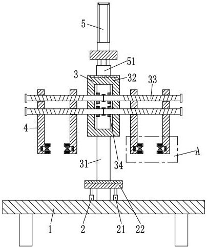
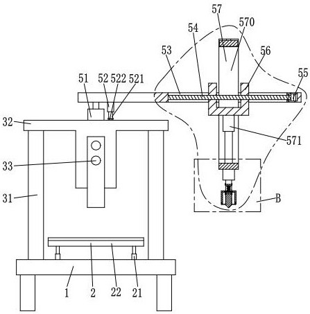
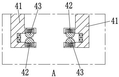
[0028] Such as Figure 1 to Figure 7 As shown, a new energy vehicle rear suspension subframe connector drilling processing machine, including a support frame 1, an auxiliary device 2, a support device 3, a fixing device 4 and a drilling device 5; the middle part of the upper end of the support frame 1 An auxiliary device 2 is provided, and the upper end of the support frame 1 is provided with a support device 3, and the support device 3 is lo...


PUM


Abstract

The invention relates to the field of auto parts processing, in particular to a new energy vehicle rear suspension sub-frame connector drilling machine, including a support frame, an auxiliary device, a support device, a fixing device and a drilling device; the invention can solve the current problem The drilling device mainly exists in the drilling process of the connection parts of the full-frame rear suspension sub-frame. The position cannot be adjusted in a portable manner. Drilling is performed on various sizes of full-frame sub-frames, and the fixing device is difficult to adjust the fixed position. Stable clamping and fixing of full-frame sub-frames of various sizes, and the current punching device is prone to generate a large amount of iron filings splashing during the process of punching full-frame sub-frames, so that the splashed iron filings On the one hand, it is easy to hurt people, and on the other hand, the splashed iron filings are not convenient for the staff to clean the workplace and recycle the iron filings later.

Description

technical field [0001] The invention relates to the field of auto parts processing, in particular to a drilling machine for connecting parts of rear suspension sub-frames of new energy vehicles. Background technique [0002] The rear suspension sub-frame is a very important part of the chassis of a household electric vehicle; Then it is connected with the main frame of the car with rigid or flexible rubber or hydraulic pads. The rear suspension sub-frame is generally composed of the main body, the stabilizer bar and the control arm. On the one hand, it can bear the vibration load of the engine, on the other hand, it can bear various impacts brought by the road conditions, and improve the stability of the car suspension system. Connection stiffness. [0003] The current automotive rear suspension sub-frame connectors mainly include Yuanbao beam, H-type and full frame type; since the automotive rear suspension sub-frame connector is mainly connected to various connectors, it...

Claims


Application Information

Patent Timeline
Patent Type & Authority Patents(China)
IPC IPC(8): B23B41/00B23B47/22B23Q3/154B23Q3/00B23Q1/25B23Q11/08
CPCB23B41/00B23Q1/25B23Q3/00B23Q3/154B23Q5/34B23Q11/08B23Q2703/10
Inventor 陈亚南
Owner 江苏特塑新能源科技有限公司
Why Eureka
Try Eureka