
System for recycling water in engine waste gas and then injecting water into inlet gas

An engine and water recovery tank technology, applied in engine components, combustion engines, exhaust gas recirculation, etc., can solve the problems of reducing the running time of the intake water injection function, increasing the water content of the engine exhaust, and increasing the burden on the engine system, reducing the Risk of abnormal combustion, reduction of NOx emissions, effect of increasing sustainability

Active Publication Date: 2021-08-17
DALIAN UNIV OF TECH
View PDF4 Cites 6 Cited by
  • Summary
  • Abstract
  • Description
  • Claims
  • Application Information

AI Technical Summary

Problems solved by technology

However, the use of intake water injection technology creates additional water demand for the engine, which requires a certain amount of water to be reserved for the engine and regular filling due to consumption, which undoubtedly increases the burden on the engine system and reduces intake water injection to a certain extent The running time of the function
In addition, the use of intake water injection also leads to a further increase in the water content in the engine exhaust
Patent CN201710527603.0 proposes an engine water injection system that recycles EGR condensed water, but only recycles the water in the EGR exhaust gas, because usually the EGR exhaust gas only accounts for a part of the exhaust gas, and changes with the operating conditions of the engine and the The demand for EGR changes, so the amount of recovered water is not only limited but also changes with the change of EGR rate, and sometimes EGR is not even performed, such as idling conditions
In addition, since there is no condenser, condensed water may continue to accumulate in the EGR cooler and piping before the EGR mixer, affecting EGR control and corroding parts

Method used


Image

  • System for recycling water in engine waste gas and then injecting water into inlet gas
  • System for recycling water in engine waste gas and then injecting water into inlet gas

Examples


Embodiment Construction

[0024] In order to more clearly illustrate the technical solutions in the embodiments of the present invention or the prior art, the following will briefly introduce the drawings that need to be used in the description of the embodiments or the prior art. Obviously, the accompanying drawings in the following description These are some embodiments of the present invention. Those skilled in the art can also obtain other drawings based on these drawings without creative work.

[0025] It should be noted that in the description of the present invention, the terms "upper", "lower", "top", "bottom", "side", "other side", "left", "right" etc. indicate The orientation or positional relationship is based on the orientation or positional relationship shown in the drawings, and is only for the convenience of describing the present invention and simplification of the description, and does not mean that devices or elements must have a specific orientation, be constructed and operated in a s...


PUM


Abstract

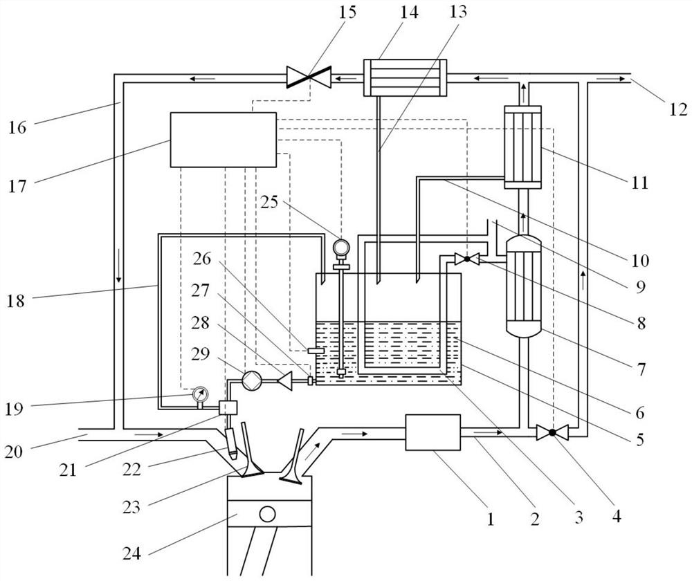
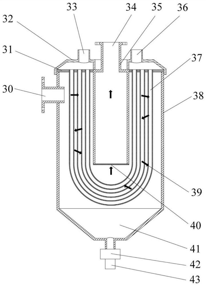
The invention relates to a system for recycling water in engine waste gas and then injecting the water into inlet gas. The system comprises a heat exchanger, a cooling liquid outlet bypass valve, a cooling liquid outlet bypass pipeline, a first water vapor condensation separator, a second water vapor condensation separator, a recycling water tank, a water spraying assembly (water injector), an exhaust aftertreatment device, an exhaust bypass valve, a terminal exhaust pipe, an EGR valve, an EGR pipeline and an electronic control unit (ECU). Moisture in the waste gas is recycled and removed, and then the recycled condensate water is sprayed into a gas inlet channel through a water injector and enters an engine combustion chamber after being mixed with fresh charge, so that the combustion temperature in a cylinder is reduced, and the risk of NOx emission and abnormal combustion is effectively reduced; and meanwhile, the sustainability and the running mileage of the air inlet water injection function of an engine are greatly improved, the cyclic utilization rate of water is increased, condensed accumulated water in an EGR system is reduced, the control precision and the stability of the EGR system are improved, and the service life of the EGR system is prolonged.

Description

technical field [0001] The invention relates to the technical field of engines, in particular to a system for recovering moisture in engine exhaust gas and injecting it into intake air. Background technique [0002] Worries about the energy crisis have forced engine technology worldwide to develop towards high performance, low fuel consumption and even energy transformation. Technologies such as supercharging, increasing compression ratio, and direct injection in cylinders have been successfully applied, and clean alternative energy sources such as hydrogen In recent years, it has also been vigorously developed in the engine. However, due to the increase in cylinder temperature, the high performance and high power of the engine and the use of alternative fuels, especially hydrogen, also increase the risk of abnormal combustion of the engine such as knocking and early ignition, which is more serious under medium-to-high load and extreme working conditions . Not only that, n...

Claims


Application Information

Patent Timeline
Patent Type & Authority Applications(China)
IPC IPC(8): F02M25/028F02M25/022F02M26/36F02M26/19F02M26/30F01N5/02
CPCF02M25/028F02M25/0222F02M25/0224F02M26/36F02M26/19F02M26/30F01N5/02Y02T10/30
Inventor 卢耀冯立岩夏雨方源张东宋湄葭曲文静王自鑫龚震
Owner DALIAN UNIV OF TECH
Learn More