
Signal transmission method of multi-channel wireless slip ring and wireless slip ring transmission system

A signal transmission, multi-channel technology, applied in the field of multi-channel wireless slip ring signal transmission method and wireless slip ring transmission system, can solve the problem of limited transmission bandwidth, single loop can not carry the transmission rate, and the maximum operating frequency of the system is limited. and other problems to achieve the effect of reducing crosstalk

Active Publication Date: 2021-08-13
저장진셍일렉트로닉스테크놀러지컴퍼니리미티드
View PDF12 Cites 0 Cited by
  • Summary
  • Abstract
  • Description
  • Claims
  • Application Information

AI Technical Summary

Problems solved by technology

However, this kind of contact slip ring has the following defects: because the brush and the electric ring are always in a state of friction when they rotate relative to each other in the two rotating mechanisms, the brush and the electric ring communicate through physical contact
Limited by device cost or hardware performance, the maximum operating frequency of the system is limited, and its transmission bandwidth is also limited. In some applications, a single loop cannot carry the required transmission rate. In this case, a combination of multiple loops is required. transmission

Method used


Image

  • Signal transmission method of multi-channel wireless slip ring and wireless slip ring transmission system
  • Signal transmission method of multi-channel wireless slip ring and wireless slip ring transmission system
  • Signal transmission method of multi-channel wireless slip ring and wireless slip ring transmission system

Examples


Embodiment Construction

[0028] The technical means adopted by the present invention to achieve the intended invention purpose are further described below in conjunction with the drawings and preferred embodiments of the present invention.

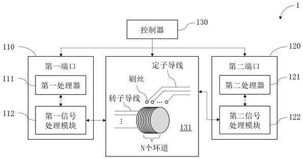
[0029] like figure 1 , figure 1 It is a block diagram of the wireless slip ring system 1 adopting the multi-channel wireless slip ring signal transmission method in the present invention. The wireless slip ring system 1 includes a controller 130 , a first processor 111 , a first signal processing module 112 , a wireless slip ring 131 , a second signal processing module 122 and a second processor 121 . The wireless slip ring 131 is connected between the first port 110 and the second port 120, the first port 110 includes the first processor 111 and the first signal processing module 112, and the second port 120 includes the second signal processing module 122 and the second Second processor 121 . Wherein, the controller 130 is respectively connected with the first ...


PUM


Abstract

The invention provides a signal transmission method of a multi-channel wireless slip ring and a wireless slip ring system using the signal transmission method. By adopting the signal transmission method of the multi-channel wireless slip ring provided by the invention, the rotor wire and the stator wire in the wireless slip ring are not conducted with each other, and signal transmission is carried out by utilizing radio wave radiation. Multiple loops of the wireless slip ring can be used at the same time, and crosstalk between the loops is reduced through an interval valuing method of setting a safe frequency band between the loops; besides, according to the signal transmission method of the multi-channel wireless slip ring, the transmission efficiency of the channel can be effectively improved and the transmission reliability of the multi-channel slip ring can be improved by setting the high carrier frequency for the loop with the high priority.

Description

technical field [0001] The invention relates to the technical field of data communication and transmission, in particular to a signal transmission method of a multi-channel wireless slip ring and a wireless slip ring transmission system. Background technique [0002] Rotational communication is a way of transmitting signals between two structures that rotate relative to each other. With the advancement of science and technology, in key equipment such as modern military industry, electronics, aviation, electric power, metallurgy, petrochemical industry, communication, network monitoring and intelligent manufacturing, a variety of rotating structures need to be used in large quantities, and signals and energy are carried out in these rotating structures. Transmission has always been a difficult and hot topic in the industry. [0003] In current applications, conductive slip rings are mainly used to realize signal transmission between two relatively rotating structures. In tr...

Claims


Application Information

Patent Timeline
Patent Type & Authority Applications(China)
IPC IPC(8): H04B5/00H01R39/64
CPCH01R39/64H04B5/72
Inventor 袁庆庆吕炳赟黄海方伟崔根强
Owner 저장진셍일렉트로닉스테크놀러지컴퍼니리미티드
Learn More