Short-focus near-eye display system

A near-eye display, short-focus technology, applied in optical components, instruments, optics, etc., to achieve the effect of shortening the overall thickness, increasing the diameter of the exit pupil, and wearing comfortably

Active Publication Date: 2021-08-13
GUANGGAN SHANGHAI TECH CO LTD
View PDF6 Cites 1 Cited by
  • Summary
  • Abstract
  • Description
  • Claims
  • Application Information

AI Technical Summary

Problems solved by technology

[0004]This invention solves the problems existing in the existing AR technology, such as large field of view, large exit pupil diameter, and the contradiction between energy efficiency and volume, and provides a short-focus near eye display system

Method used


Image

  • Short-focus near-eye display system
  • Short-focus near-eye display system
  • Short-focus near-eye display system

Examples


specific Embodiment approach 1

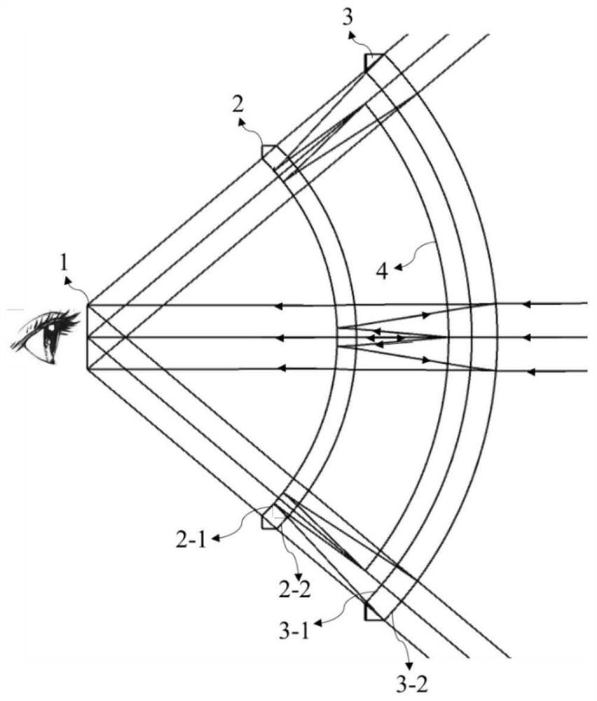
[0045] Specific implementation mode 1. Combination Figure 1 to Figure 19 Describe this embodiment, such as figure 1 As shown, a short-focus near-eye display system is mainly composed of a microdisplay 4, a convex partial reflector 2 and a concave partial reflector 3, wherein the microdisplay 4 is between the convex partial reflector 2 and the concave partial reflector 3, and Shine toward the eyes. The microdisplay 4 can be a transparent display 4a, or a rotating linear display 4b. The part of the mirror near the eye is a convex mirror, and the part of the mirror far away from the eye is a concave mirror. The concave side of the microdisplay 4 emits light, which is reflected by one of the surfaces of the convex partial reflector 2, that is, the inner surface 2-1 of the convex partial reflector or the outer surface 2-2 of the convex partial reflector, and after passing through the microdisplay 4, it is partially reflected by the concave surface The mirror 3 reflects and pass...

specific Embodiment approach 2

[0080] Specific embodiment two, combine Figure 20 to Figure 24 This embodiment will be described. The structure and rotation method of the micro-display 4 in this embodiment are similar to those in Embodiment 1, and will not be repeated here.

[0081] Such as Figure 20 As shown, a short-focus near-eye display system is mainly composed of an outer micro-display 4d or an outer flat micro-display 4f, a convex partial reflector 2 and a concave partial reflector 3, wherein the outer micro-display 4d or the outer straight micro-display 4f The concave part reflector 3 is away from the outer side of the direction of human eyes, and emits light toward the eyes. Such as Figure 20 As shown, its position can be close to the outer surface 3-2 of the concave part reflector, such as Figure 21 and Figure 22 As shown, there may also be a certain interval, such as 3mm. The outer micro-display 4d or the outer straight micro-display 4f can be a transparent display or a rotating linear d...


PUM


Abstract

A short-focus near-to-eye display system relates to the technical field of near-to-eye display, solves the problems of large field angle, large exit pupil diameter, contradiction between energy efficiency and volume and the like in the existing AR technology, and comprises a micro display, a convex surface part reflector or a plane part reflector, and a concave surface part reflector, wherein the micro-display is positioned between the convex surface part reflecting mirror and the concave surface part reflecting mirror or the micro-display is positioned between the plane part reflecting mirror and the concave surface part reflecting mirror, and emits light towards an eye pupil position; the reflecting mirror close to the eye pupil is a convex partial reflecting mirror or a plane partial reflecting mirror, and the reflecting mirror far away from the eye pupil is a concave partial reflecting mirror; and the micro display is a transparent display or a rotary linear display. Through two times of reflection, the size of the micro-display is increased optically, the manufacturing difficulty of the micro-display is reduced, the precision required by rotation is reduced, and higher resolution is supported. Through the turning effect of the plane mirror, the thickness of the glasses can be reduced to the maximum extent, and thinning is realized.

Description

technical field [0001] The invention relates to the technical field of near-eye display, in particular to a short-focus near-eye display system. Background technique [0002] Augmented reality (AR for short) is called the third-generation computing platform, which can enlarge the image of the micro-display through small-sized glasses to provide users with a super-large 3D image, and at the same time, the displayed image can be integrated with the real environment. It has a very wide range of applications in daily life and industry. [0003] At present, there are a variety of AR technologies, including free-form prisms, off-axis catadioptric structures, waveguide glasses, etc. Due to various constraints, they cannot solve the contradiction between large field of view, large exit pupil diameter, energy efficiency and volume. The present invention solves the above problems by using spherical symmetry. Based on the previously applied patent technology (patent number: 2020207424...

Claims


Application Information

Patent Timeline
Patent Type & Authority Applications(China)
IPC IPC(8): G02B27/01
CPCG02B27/0172G02B27/0983G02B27/286G02B27/0012G02B5/10
Inventor 杨建明
Owner GUANGGAN SHANGHAI TECH CO LTD
Why Eureka
Try Eureka