
Exhaust waste heat recovery device and automobile

A recovery device and exhaust waste heat technology, which is applied in the direction of exhaust devices, mufflers, internal combustion piston engines, etc., can solve problems such as coolant leakage, heat exchange pipeline damage, pressure increase, etc., to avoid heat radiation and heat Transmitting, avoiding damage, suppressing the effect of boiling

Active Publication Date: 2021-08-13
GUANGZHOU AUTOMOBILE GROUP CO LTD
View PDF9 Cites 0 Cited by
  • Summary
  • Abstract
  • Description
  • Claims
  • Application Information

AI Technical Summary

Problems solved by technology

[0003]Currently, in order to reduce fuel consumption and improve emissions, some models choose to be equipped with exhaust waste heat recovery devices. The closer the waste heat recovery device is to the engine, the higher the surface temperature of the exhaust pipe around the waste heat recovery will be after the engine stops working, and the high temperature wall will continue to exchange heat with the heat exchanger that stops circulation. In severe cases, the coolant in the heat exchanger will boil and the pressure will increase. , damage the heat exchange pipeline, and eventually cause the coolant to leak

Method used


Image

  • Exhaust waste heat recovery device and automobile
  • Exhaust waste heat recovery device and automobile

Examples


Embodiment Construction

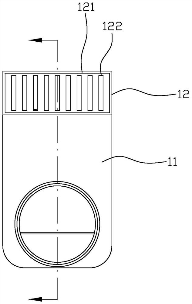
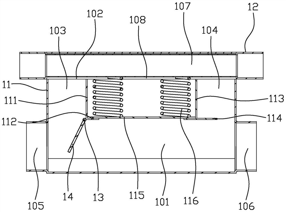
[0020] figure 1 is a schematic partial side view of the exhaust waste heat recovery device of the present invention, figure 2 yes figure 1 The cross-sectional schematic diagram of the exhaust waste heat recovery device shown, as shown in figure 1 and figure 2 As shown, the exhaust waste heat recovery device includes an exhaust casing 11 and a heat exchanger 12, the exhaust casing 11 is provided with an exhaust passage 101, and the heat exchanger 12 is arranged on the top of the exhaust casing 11. The first partition 111, the second partition 113, the movable plate 115 and the elastic member 116, the first partition 111 is arranged opposite to the second partition 113, and the first partition 111 and the second partition 113 are connected to the exhaust casing On the inner wall of 11, a heat exchange inlet passage 103 is formed between the first partition 111 and the inner wall of the exhaust shell 11, and the heat exchange inlet passage 103 communicates with the exhaust p...


PUM


Abstract

An exhaust waste heat recovery device comprises an exhaust shell and a heat exchanger. An exhaust channel is arranged in the exhaust shell, the heat exchanger is arranged at the top of the exhaust shell, a first partition plate, a second partition plate, a movable plate and an elastic piece are arranged in the exhaust shell, and the first partition plate and the second partition plate are oppositely arranged and connected to the inner wall of the exhaust shell; a heat exchange air inlet channel is formed between the first partition plate and the inner wall of the exhaust shell and communicates with the exhaust channel and the heat exchanger, a heat exchange air outlet channel is formed between the second partition plate and the inner wall of the exhaust shell and communicates with the exhaust channel and the heat exchanger, and the movable plate is movably arranged between the first partition plate and the second partition plate; and the elastic piece is connected between the heat exchanger and the movable plate, and airflow in the exhaust channel and the heat exchanger can push the movable plate. According to the exhaust waste heat recovery device, heat radiation and heat transfer of the movable plate to the heat exchanger can be avoided. The invention also relates to an automobile.

Description

technical field [0001] The invention relates to the technical field of engine waste heat recovery, in particular to an exhaust waste heat recovery device and an automobile. Background technique [0002] With the stricter emission regulations and the further reduction of fuel consumption, exhaust waste heat recovery has become a favorable way to improve emissions and reduce fuel consumption. However, after the exhaust system with the exhaust waste heat recovery device stops working, the wall surface temperature of the exhaust system is very high (over 500°C), and the high temperature wall surface still continues to exchange heat with the coolant that has stopped circulating. [0003] At present, in order to reduce fuel consumption and improve emissions, some models choose to be equipped with exhaust waste heat recovery devices. At the same time, in order to maximize the recovery efficiency, it is necessary to place the waste heat recovery device as close as possible to the en...

Claims


Application Information

Patent Timeline
Patent Type & Authority Applications(China)
IPC IPC(8): F02G5/02F01N5/02
CPCF02G5/02F01N5/02Y02T10/12
Inventor 黄兴来张凯曾志新曾恩山张宁
Owner GUANGZHOU AUTOMOBILE GROUP CO LTD
Learn More