Novel water cooling structure of water pump motor

A water pump motor and water cooling technology, which is applied in electromechanical devices, electrical components, electric components, etc., can solve the problems of high temperature failure of permanent magnets, magnetic attenuation of permanent magnets, damage of water pumps, etc., to avoid high temperature failure or damage, ensure work efficiency, Ease of maintenance and installation

Active Publication Date: 2021-08-10
中擎电机有限公司
View PDF8 Cites 1 Cited by
  • Summary
  • Abstract
  • Description
  • Claims
  • Application Information

AI Technical Summary

Problems solved by technology

[0004] In order to solve the technical problem that the water pump motor in the prior art cannot be well cooled when it is working, resulting in the magnetic attenuation of the permanent magnet inside the rotor, affecting the working efficiency of the water pump, and even causing damage to the water pump due to high temperature failure of the permanent magnet, the invention provides a new type of water pump Motor water cooling structure

Method used


Image

  • Novel water cooling structure of water pump motor
  • Novel water cooling structure of water pump motor
  • Novel water cooling structure of water pump motor

Examples


Embodiment 1

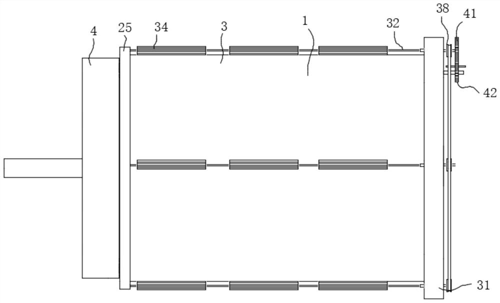
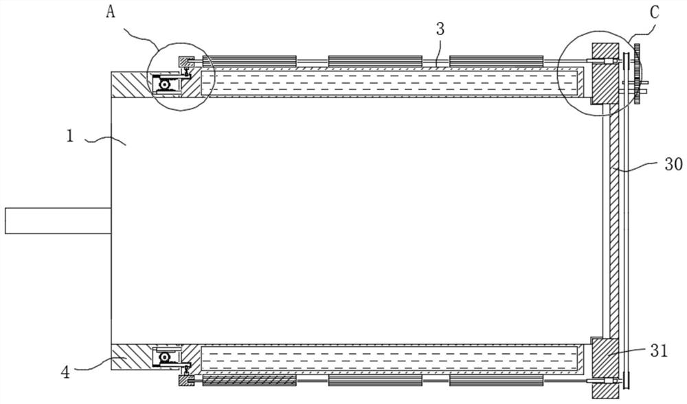
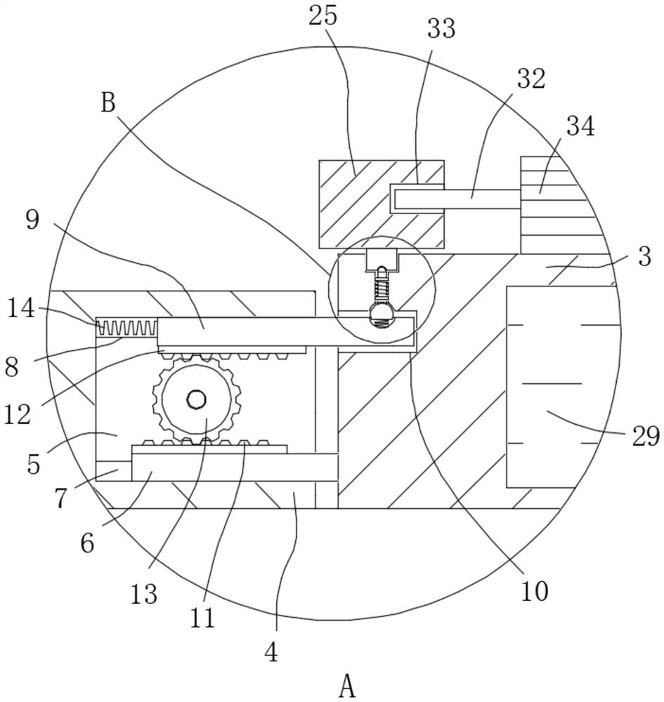
[0030] Please combine Figures 1 to 7 The new water pump motor water-cooled structure includes a housing 1 and a heat exchange barrel 3 that is attached to the outer peripheral side of the casing 1, and the casing 1 is a housing of the water pump motor. The heat exchange cylinder 3 is adapted to the casing 1, so that the inner casing wall of the heat exchange tube 3 is completely bonded to the outer wall of the casing 1, and the amount of heat near the stator can be well conducted when the motor is operated. The inner surface of the cylinder wall of the heat exchange tube 3 has a flow path cavity 29 surrounding the casing 1, and the flow diaphragm 29 extends in the axial direction of the casing 1, and is surrounded by the outer side of the casing 1, so that the refrigerant is in the flow channel cavity 29 The inner average can be flowable to heat transfer to each position on the outer peripheral side of the casing 1. The flow path cavity 29 is housed in a refrigerant of the casing ...

Embodiment 2

[0048] This Example 2 is a modified scheme of Example 1. Specifically, the side wall of the heat exchange cylinder 3 is switched from the respective side wall, and the inlet of the inner portion of the interior of the flow path cavity 29 is changed. The water bar is provided with a water outlet (not shown) on the side wall of the other end of the hot tube 3. Cooling water having pressure is conveyed through the flow of the heat exchange tube 3 through the inlet.

[0049] Valves are mounted on the inlet and outlet ports in this embodiment. When the water pump is used to transport water, the inlet of the flow channel chamber 29 can be connected to the water pump of the water pump by a conduit, and the effluent of the flow channel cavity 29 is connected to the water pump of the water pump through the catheter, so that in order to flow Cooling water having a certain pressure is delivered within the road cavity 29.

[0050] When the cooling water having the pressure is flowing into the...


PUM


Abstract

The invention relates to the technical field of water cooling structures, and discloses a novel water cooling structure of a water pump motor. The novel water cooling structure comprises a machine shell and a heat exchange cylinder arranged on the peripheral side of the machine shell in an attached and sleeving mode, wherein the inner surface of the cylinder wall of the heat exchange cylinder is provided with a flow channel cavity surrounding the machine shell, a refrigerant used for heat exchange and cooling of the machine shell is contained in the flow channel cavity, the peripheral side of the machine shell is sleeved with a fixing ring, at least one open groove is formed in the side, facing the heat exchange cylinder, of the fixing ring, a first inserting groove and a second inserting groove which are parallel to the axial direction of the heat exchange cylinder are oppositely formed in the groove wall of the open groove, a second inserting strip is arranged in the second inserting groove in a sliding mode, and one end of the second inserting strip is elastically connected with the corresponding groove wall of the second inserting groove. By means of the heat exchange cylinder additionally arranged on the machine shell and a plurality of heat dissipation blocks on the heat exchange cylinder, heat conducted to the machine shell by a stator can be subjected to heat exchange and cooling, so the water pump motor can work at a normal operating temperature, working efficiency is guaranteed, and the water pump motor is prevented from losing efficacy or being damaged at a high temperature.

Description

Technical field [0001] The present invention relates to the technical field of water-cooled structures, and more particularly to a new water-cooled structure of a new pump motor. Background technique [0002] The water pump is a mechanical transport that transports liquid or carries a liquid boost. It transmits the mechanical energy or other external energy of the original motivation to the liquid, which increases the energy of the liquid, mainly used to convey the liquid, oil, acid, acid, alkali, emulsion, suspension, and liquid metals. It is also possible to deliver liquid, gas mixtures, and liquids containing suspended solids. [0003] However, the water pump motor in the prior art, the motor rotor thermal cycle can only be transmitted by the motor rotor to the motor, and the stator is transmitted to the outside by the motor shell, and the heat dissipation efficiency is low. As the water pump is running at high speed, the motor rotor does not have good cooling, the magnetic ma...

Claims


Application Information

Patent Timeline
IPC IPC(8): H02K5/20H02K5/18H02K9/19
CPCH02K5/20H02K5/18H02K9/19
Inventor 林波宋泽新叶灵荣林娜金新兵
Owner 中擎电机有限公司
Why Eureka
Try Eureka