
Multi-mode combined power cycle system based on transcritical CO2 and method

A combined power and circulation system technology, applied in the cooling of machines/engines, turbines/propulsion devices, engine components, etc., can solve the problems that the engine cannot further increase the Mach number, the structure of the pre-cooling system is large and complex, and the pre-cooling capacity is insufficient , to maximize energy utilization, reduce structural complexity, and facilitate portability and storage

Active Publication Date: 2021-08-10
NANJING UNIV OF AERONAUTICS & ASTRONAUTICS
View PDF6 Cites 2 Cited by
  • Summary
  • Abstract
  • Description
  • Claims
  • Application Information

AI Technical Summary

Problems solved by technology

The "Scimitar" engine combines the characteristics of the turbine engine and the ramjet engine, making it work in a wider speed range and a wider working airspace, while avoiding the problem of "thrust gap" at the mode transition point of the TBCC engine and avoiding the low-speed section of the RBCC engine Insufficient thrust gain in the ejection mode, all parts of the engine in the entire working area can achieve high-efficiency work, but the "scimitar" engine chooses helium as the cooling medium, due to its low density and effective use of sensible heat transfer capacity The characteristics will inevitably lead to insufficient pre-cooling capacity and the large and complex structure of the pre-cooling system, which puts forward high requirements on the thermal management technology of the aircraft. One of the key factors, so designing an aircraft with strong pre-cooling capacity and simple structure of the pre-cooling system has become an important direction for the next development of turbo-ramjet combined engines

Method used


Image

  • Multi-mode combined power cycle system based on transcritical CO2 and method

Examples


Embodiment Construction

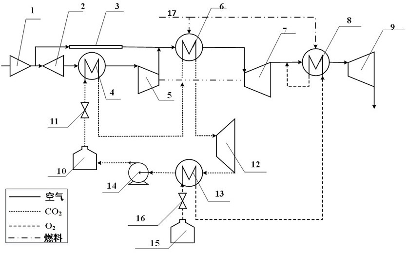
[0014] Refer below figure 1 Describe the operation process of the multi-mode combined power cycle system based on transcritical CO2.

[0015] figure 1 It is a multi-mode combined power cycle system based on transcritical CO2 proposed by the present invention. The working process of the system is as follows: It can be divided into 3 modes (low speed mode, high speed mode and super high speed mode).

[0016] Turbine mode: the flight Mach number is 0~0.9; the first switch 11 and the second switch 16 are closed, and the outer duct 3 is opened by regulating the intake duct 1, and the air enters the intake duct 1 and is divided into the inner duct 2 And in the outer duct 3, the air in the outer duct 3 directly enters the main combustion chamber 6, the air in the inner duct 2 enters the compressor 5 for boosting, and the high-pressure air enters the main combustion chamber 6 for combustion, high temperature and high pressure The air passes through the air turbine 7 to perform work...


PUM


Abstract

The invention discloses a multi-mode combined power cycle system based on transcritical CO2 and a method, and belongs to the field of aviation power propulsion. According to the multi-mode combined power cycle system based on transcritical CO2 and the method, a turbine engine, a ramjet and the supercritical CO2 Brayton cycle are coupled, so that a hypersonic aircraft can be switched in multiple modes, and therefore the purpose of wider-range work is achieved. The system comprises an air inlet channel (1), an inner duct (2), an outer duct (3), a precooler (4), a compressor (5), a main combustion chamber (6), an air turbine (7), an afterburner (8), a spray pipe (9), a CO2 turbine (12), a condenser (13), a pump (14), a liquid CO2 tank (10), a liquid oxygen tank (15), a first switch (11) and a second switch (16). According to the combined power cycle, transcritical CO2 closed heat energy gradient recovery Brayton cycle is adopted in a super-precooling flight mode, and liquid oxygen is utilized for condensation, so that the energy utilization of the system is maximized; and in addition, supercritical CO2 is adopted as a pre-cooling working medium to replace traditional helium, the system structure is more compact, the thrust is larger, and the wider-range working requirement can be rapidly met.

Description

technical field [0001] The invention relates to a transcritical CO2-based multi-mode combined power cycle system and method, and belongs to the field of improvement of aero-engine combined power cycle systems. Background technique [0002] For hypersonic long-range cruising flight, the power system needs to meet the optimum performance within the flight envelope of Ma0~5, and it is difficult for the traditional single-form engine to achieve stable operation in the full speed range. The combined power cycle developed in recent years, such as the turbo ramjet combined cycle engine, can meet the requirements of wide speed range work, but when the flight speed increases, it will cause the total temperature of the inlet airflow to increase, and at the same time, it is limited by the material. There is an upper limit to the total inlet temperature of the air turbine, so the increase in the total temperature of the incoming air will gradually reduce the heating capacity of the air,...

Claims


Application Information

Patent Timeline
IPC IPC(8): F02C7/18F02C7/08F02C7/057
CPCF02C7/18F02C7/08F02C7/057
Inventor 葛浩岳晨范育新于文博姚尚军
Owner NANJING UNIV OF AERONAUTICS & ASTRONAUTICS
Learn More