
Sewage treatment process and sewage treatment device

A sewage treatment device and technology for sewage treatment, applied in biological water/sewage treatment, water/sludge/sewage treatment, return water treatment, etc., can solve the problem that the effect of denitrification and phosphorus removal is difficult to be further improved, and the biological metabolism function and activity decline. , the phosphorus removal effect is not satisfactory, etc., to reduce the sludge SVI, improve the microbial activity, and prolong the sludge age.

Active Publication Date: 2021-08-10
CENT & SOUTHERN CHINA MUNICIPAL ENG DESIGN & RES INST
View PDF8 Cites 6 Cited by
  • Summary
  • Abstract
  • Description
  • Claims
  • Application Information

AI Technical Summary

Problems solved by technology

Although the denitrification effect of this process has been significantly improved, there are still some technical bottlenecks that cannot be broken through
[0005] The process does not set an anaerobic zone, and some refractory organic matter in the influent cannot be fully utilized by denitrifying bacteria; the phosphorus removal effect is not satisfactory
In addition, due to the discharge of excess sludge in the secondary settling tank, the concentration of activated sludge in the reaction zone will decrease; at the same time, due to the lack of oxygen and concentration of the sludge at the bottom of the secondary settling tank, the biological metabolic function and activity will decrease significantly, and it will flow back to the deficient The recovery of the oxygen zone is slow, and the effect of nitrogen and phosphorus removal is difficult to further improve

Method used


Image

  • Sewage treatment process and sewage treatment device
  • Sewage treatment process and sewage treatment device

Examples


Embodiment 1

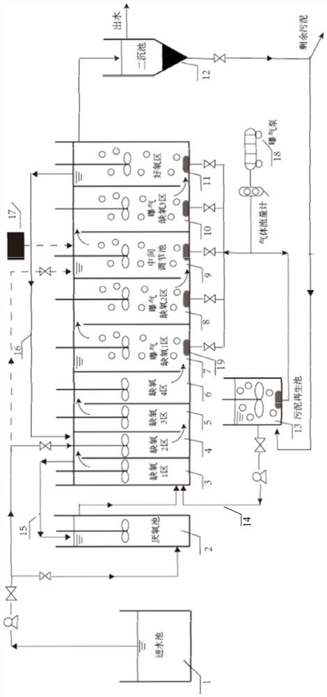
[0038] The present invention proposes a sewage treatment process, with reference to figure 1 , including the following steps:

[0039] S10. The external sewage is sent to the anaerobic pool and the anoxic pool respectively in two ways. The sewage in the anaerobic pool is treated by ammonification and denitrification and enters the anoxic pool for deep denitrification.

[0040] The sewage enters the anoxic pond after ammonification, denitrification and phosphorus release treatment in the anaerobic pond; the organic matter degradation, denitrification, deep denitrification and phosphorus release treatment are carried out in the sewage in the anoxic pond; part of the sewage in the anoxic pond is refluxed into the anaerobic tank. In this step, the anaerobic tank refers to a non-aerobic tank, and the dissolved oxygen concentration is generally less than 0.2mg / L. Microorganisms absorb organic matter and release phosphorus in this tank. Anoxic pool refers to a non-oxygenated pool, ...

Embodiment 2

[0048] This embodiment is an improvement based on embodiment 1, with reference to figure 1 , in step S20, said another road successively passes through the anoxic aeration tank and the aerobic zone to carry out sufficient nitrification and also includes the following steps: S21. The sewage in the anoxic aeration tank enters the intermediate adjustment tank, and the external sewage enters from the third road Enter the intermediate adjustment tank, and the sewage in the intermediate adjustment tank enters the aerobic zone after conditioning treatment. In this step, the external sewage is rich in organic matter, which can be directly input into the intermediate adjustment tank to provide carbon sources for the activities of microorganisms in the tank and the aerobic tank, which can further save the input of external carbon sources.

Embodiment 3

[0050] In step S20, the other path sequentially passes through the anoxic aeration tank and the aerobic zone to carry out sufficient nitrification, and further includes the following steps: the other sewage from the anoxic tank passes through the aeration and anoxic zone one and the anoxic zone of the anoxic aeration tank in turn. After aeration and anoxic zone two, it enters the intermediate adjustment tank, and the sewage in the intermediate adjustment tank flows into the aerobic zone through the aeration and anoxic zone three. In this step, the external sewage is rich in ammonia nitrogen, and the three aeration and anoxic zones can be set to perform deep denitrification of the newly added sewage, further improving the denitrification efficiency.


PUM


Abstract

The invention discloses a sewage treatment process and a sewage treatment device. The process comprises the steps: S10, dividing sewage into two paths to be conveyed to an anaerobic tank and an anoxic tank respectively, and treating the sewage in the anaerobic tank and enabling the sewage to enter the anoxic tank to be subjected to deep denitrification; S20, enabling sewage in the anoxic tank to flow out in two paths: one path flows back to the anaerobic tank, and the other path sequentially passes through the anoxic aeration tank and the aerobic zone to be fully nitrified; S30, enabling the sewage in the aerobic zone to flow out in two paths: one path flows back to the anoxic tank, and the other path is input into a secondary sedimentation tank for mud-water separation to form precipitated sludge; S40, enabling the precipitated sludge to flow back to the sludge regeneration tank, and carrying out the aeration treatment in the sludge regeneration tank to form activated sludge; S50, enabling the activated sludge in the sludge regeneration tank to flow back to the anoxic tank. According to the invention, sewage is subjected to multi-path water inlet, multi-path backflow, controlled aeration, conditioning and recarburization treatment, and sludge is subjected to activation and backflow treatment, so that the activity of different target bacterial colonies in each area can be improved to realize high-efficiency denitrification, and the aeration process is more energy-saving.

Description

technical field [0001] The invention belongs to the field of sewage treatment, and in particular relates to a sewage treatment process and a sewage treatment device. Background technique [0002] In recent years, with the rapid development of my country's economy and society, more and more sewage containing nitrogen and phosphorus has entered natural water bodies, causing the problem of eutrophication in water bodies to become increasingly serious, and water pollution control and treatment are urgently needed. The aggravation of water environmental problems has led the government to promulgate a series of stricter pollutant control strategies and discharge standards. Therefore, the search for nitrogen and phosphorus removal technology with high efficiency, low consumption and no secondary pollution is a hot research topic in the field of water treatment. [0003] Traditional A / O, A2 / O and UCT processes have poor denitrification and phosphorus removal effects, large floor sp...

Claims


Application Information

Patent Timeline
Patent Type & Authority Applications(China)
IPC IPC(8): C02F3/30C02F3/00
CPCC02F3/302C02F3/308C02F3/006C02F2301/04Y02W10/10
Inventor 董文艺曹琳侯子泷刘华光谢晋黎柳记刘向荣戴仲怡
Owner CENT & SOUTHERN CHINA MUNICIPAL ENG DESIGN & RES INST
Learn More